How to Comprehend Electrical Relays and Solid-State Relays for Switching
Electrical relays can be divided into two categories, namely Electromechanical Relays and Solid-State Relays.
Electromechanical Relays
Electromechanical relays are the devices which are electromagnetic in nature and convert the magnetic flux, which is generated by the low input power DC or AC signal around the relays, into the mechanical force which is used to operate the electrical contacts in the relays. The most commonly used electromechanical relays have a circuit; wound around an absorptive iron core; which is known as the primary circuit.
The iron core has a both fixed part called yoke, and an armature which is a moveable spring-loaded part, which closes the air gap between moveable armature and fixed electrical coil, hence completes the magnetic field circuit. The armature closes the contacts that are attached to it and can freely move between the generated magnetic field due to its pivot or hinged position. A spring or springs are connected between the armature and yoke to generate the return stroke to restore the connects to their original position when the relay coil is de-energized or is in its off state.
Construction of Electromechanical Relay
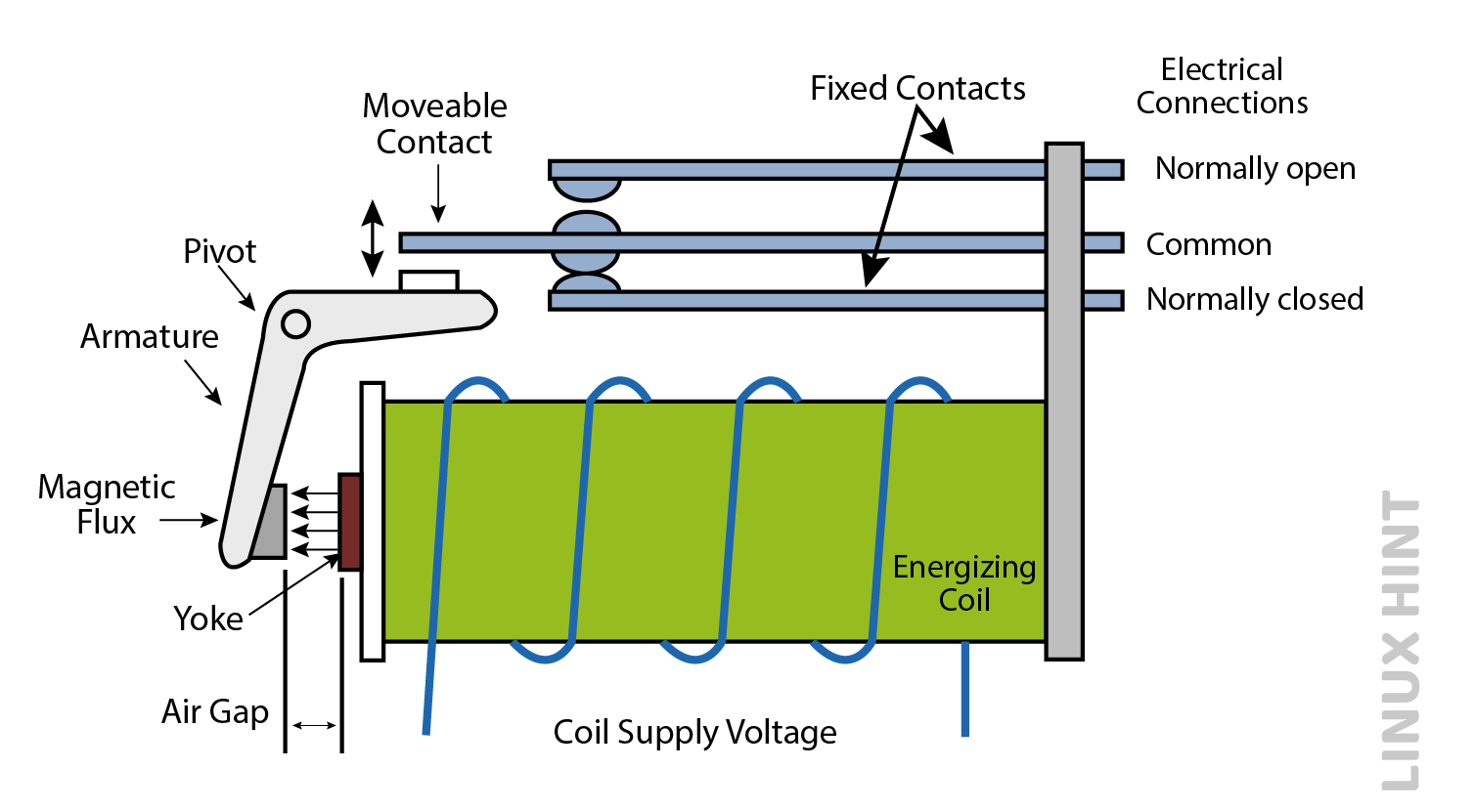
The above given figure shows the simple relay which has two sets of electrically conductive contacts. Relays may be “Normally Open” or “Normally Closed”. The pair of contacts is characterized as Normally Open or make contacts, and one pair is characterized as Normally closed or break contacts. In Normally Open contacts the contacts are open when there is no input power, they are closed only when there is a field current, while in Normally Closed contacts the contacts are closed when there is no input power, they are open only when there is a field current. These terms are by default used for the de-energized circuits that are in their off states.

The contacts of relays are electrically conductive pieces of metal, when they contact each other they complete the circuit and conduct the current flow through the circuit just like switches. In open state they have a very high resistance in mega ohms and act as an open circuit, while in closed state they act as a closed switch, and ideally, they should have a zero resistance, but there is always a certain amount of contact resistance which is termed as “ON resistance”.
New contacts and relays have a very low ON resistance because their tips are neat and new, but over time this resistance will increase. There is an arching effect observed in the contacts which is referred to as the damage in the tips of contacts if they are not properly protected from high capacitive and inductive loads. As the current will flow through the contacts when they are connected, and arching effect if not controlled will keep increasing making the resistance large which eventually results in the teared and non-conducting contacts even when they are in closed state.
To reduce the arching effects and high “ON resistance” in conducts, and improve their life span, the modern conduct tips are made of or coated with different silver alloys. Some of them include Ag (fine silver), AgCu (silver copper), AgCdO (silver cadmium oxide), AgW (silver tungsten), AgNi (silver nickel), Platinum, Gold, and Silver Alloys and AgPd (silver palladium).
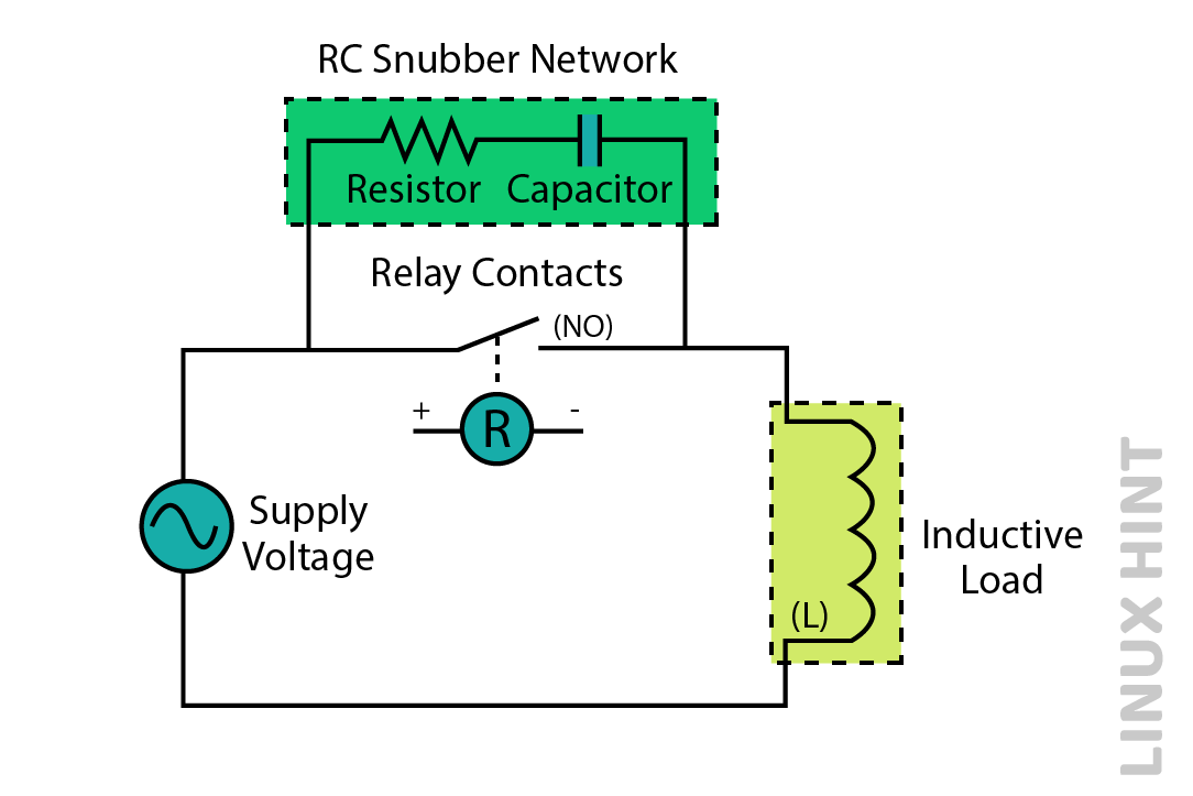
The long life of relay contacts can be achieved by using the filtering technique, which is done by adding a Resistor Capacitor Network known as Snubber Circuit in parallel with relay contact tips. This RC circuit will short-circuit the high voltage, which will eventually suppress any arching effect.
Classification of electromechanical relays based on contact types
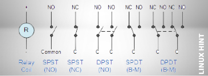
As the NO and NC describe how the contacts are connected, they can also be classified based on their actions. They can be made by joining one or more switch contacts also referred to as poles, which can be further connected by energizing the relay coils giving rise to four different contact types given as:
| Type | Description | Application |
| Single Pole Single Throw (SPST) | It has a single pole and single output. It will be either closed or completely disconnected, there is no in between. | They are perfect for on and off switching. |
| Single Pole Double Throw (SPDT) | It has a single input and two dissimilar outputs. It can control two dissimilar circuits through a single input. | They are used in control circuits and PLC system output switches. |
| Double Pole Single Throw (DPST) | It has two inputs and two outputs. Each of its terminals can either be in the off position (open) or in the on position (closed) . | They are used as thermostats to control electric heating loads. |
| Double Pole Double Throw (DPDT) | It has two inputs and four outputs. Each of the inputs corresponds to two outputs.it can control two different circuits at a time. | They are used in power supply selection and lighting control etc. |
The Solid State Relays
The Solid-State Relays do not have any moving parts, but they use the optical and electrical characteristics of solid-state semiconductors to create isolation and perform switching functions. As they have no moving parts unlike electromechanical relays, there is no wear and tear of the components. They also provide complete isolation between output and input contacts, having very high resistance at open state and very low at conducting state. They are similar in functionality to electromechanical relays, as they also perform switching operations. They are compatible with most IC logic families without using additional amplifiers, drivers, or buffer circuits, due to their low input control power requirements. However, they require being suitably mounted on heat sinks to avoid overheating.
Solid State Relay
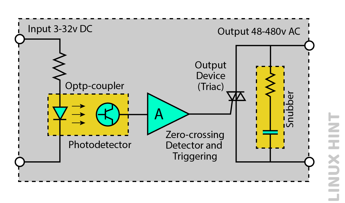
At the zero-crossing point of the AC sinusoidal waveform, the AC type Solid State Relay turns “ON” and it prevents high incoming currents. While switching high capacitive and inductive loads, RC Snubber circuit is used to eliminate the noise and voltage transient spikes. As the output switching device is a solid-state semiconductor relay, the voltage drop at output is very high which causes the demand of heat skin to avoid circuit overheating and damage.
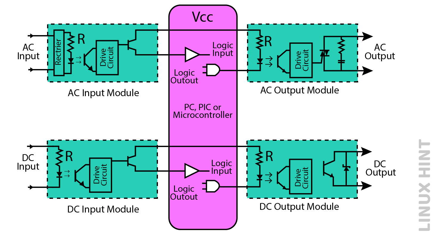
Input/Output Interface Modules
Input/Output interface modules are a special design of solid-state semiconductor relays to connect microcontrollers, computers and PICs to real world switches and loads. There are four basic types of I/O modules, CMOS logic level output or AC/DC Input voltage to TTL, CMOS logic input to an AC or DC Output voltage and TTL. These modules contain all the mandatory circuitry for providing isolation and a complete interface within one small device. They are accessible as separate solid-state modules, or they are integrated into devices of 4, 8 or 16 channels.
Comparison table between Electromechanical and Solid-State Semiconductor Relays
Electromechanical Relays use mechanical contacts for switching and have moving parts, while Solid State Semiconductor Relays use semiconductor devices for switching and do not have any moving parts.
| Electromechanical Relays | Solid State Semiconductor Relays |
| They use magnetic fields, coils, springs, and mechanical contacts to perform switching. | They use no moving parts, instead use optical and electrical properties of the solid-state semiconductors. |
| Due to the moving parts, they undergo damage to the components. | They do not undergo wear and tear of components. |
| They have a limited contact life cycle and take up a big room. Also, they have slow switching speed. | There are no such limitations of greater space and slow speed. |
| A voltage with small input can be used to control a large output voltage. | A voltage with small input can be used to control a large output voltage. |
| They are cost-efficient. | They are expensive. |
| They can switch small voltage loads and high frequency signals such as audio and video signals. | They cannot switch high frequency and small voltage loads signals such as video and audio signals. |
| They have most common applications in automobiles and domestic electronic appliances etc. | They have most common applications in switching of AC loads such as light dimming, motor speed control etc. |
Conclusion
An electrical relay is a switch which turns the electric circuit on and off through an external electrical signal. They can control a high electric current through a low power signal, also classed as transducers, because of their ability to change one physical quantity into another. Electromechanical Relays use magnetic fields, coils, springs, and mechanical contacts to perform switching. Due to the moving parts, they undergo damage to the components.
They have a limited contact life cycle and take up a lot of room, also they have slow switching speed while Solid State Semiconductor Relays use no moving parts instead using electrical and optical properties of solid-state semiconductors. They do not undergo wear and tear of components, but they are expensive.
Source: linuxhint.com