How to Build a Passive RC Low Pass Filter
Filters are RC circuits that can pass frequencies of certain signals while attenuating signals of all other frequencies. Passive elements are composed of resistors, inductors, or capacitors.
RC Low Pass Filter
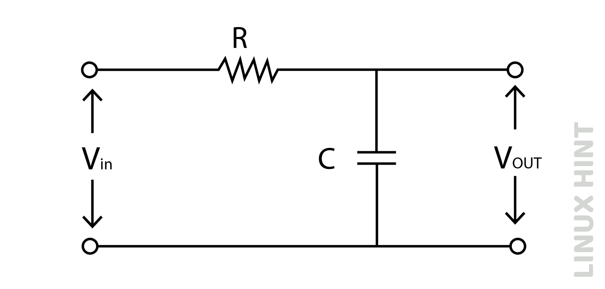
A low-pass filter passes low-frequency and will allow signals ranging from zero hertz up to cut-off frequency point ‘fc’. The low-pass RC filter comprises a resistor and a capacitor connected in series. The input voltage is connected with a resistor in series, while the output voltage is taken across the capacitor as shown below:
Capacitive Reactance
The capacitor shows a change in behavior with frequency, but the resistor remains independent of any changes in frequency. The capacitor opposes any current flow in this circuit, and this property of the capacitor is known as its capacitive reactance. The capacitive reactance of the RC circuit will be minimal when the frequency is low, however, it will be maximum when the frequency is substantially high, the capacitive reactance is expressed as:

Here f is frequency, C is capacitance and Xc is capacitive reactance.
Impedance Calculation
The impedance of the RC filter circuit is calculated as follows:

Output Voltage Calculation
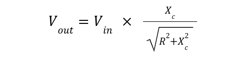
Since the impedance is given by:

Substituting in the above equation:

Frequency Response
The frequency response of the passive RC low pass filter is shown below:
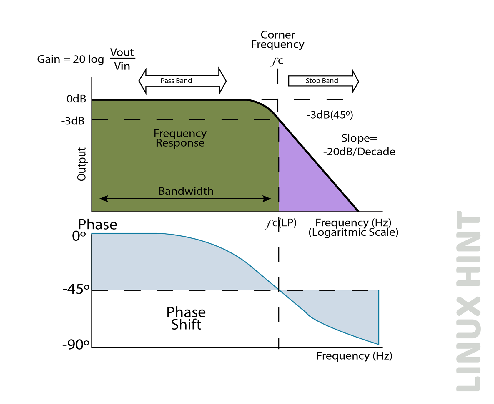
The frequency response remains flat till the cut-off frequency point fc. All input signals are passed directly to the output before the cut-off frequency point, and the low-pass RC filter has a unity gain in this range. The frequency plot slopes downwards as soon it reaches the cut-off frequency point, at the rate of -20db/Decade. Above the cut-off frequency point, all higher frequencies are blocked by this filter. This is due to the reason that at very high frequencies, capacitive reactance falls quite low, and the capacitor just acts as a short circuit providing zero output at higher frequency cases.
Cut-Off Frequency, Phase Shift, and Time Constant
The cut-off frequency of the RC low pass filter is expressed below:

The above expression shows that the cut-off frequency can be changed by selecting different values of both resistor and capacitor.
The phase shift of the RC low pass filter is expressed below:

The time constant of the RC low pass filter is expressed below:

Second Order Low Pass RC Filter
To enhance the filtering capabilities of low pass RC filter, a cascade of another RC combination may be added to the original RC circuit as shown below:
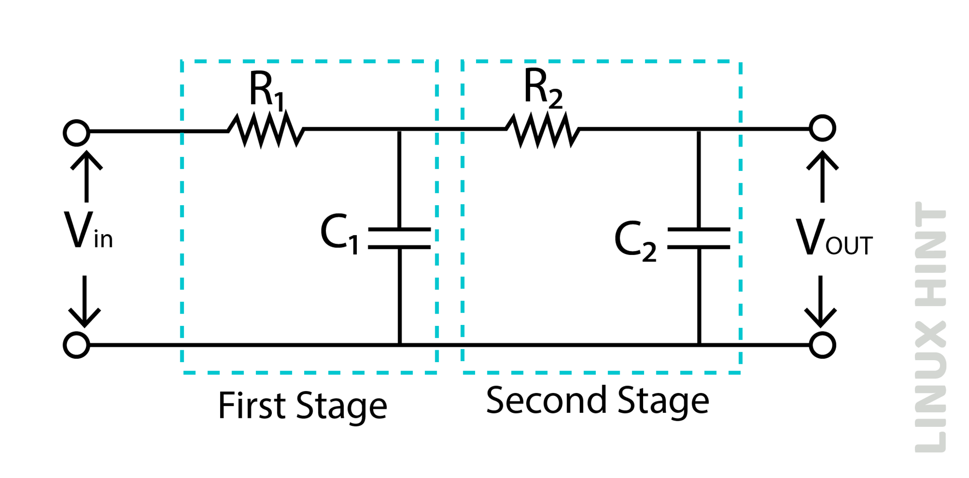
A second-order RC filter is obtained by adding a second RC combination stage as shown above. The first order-based RC filter provides a slope at -20db/decade, while a second-order filter provides a slope at -40db/decade, the passive low pass second-order filter gain is given by:

The cut-off frequency in case of second order low pass filter is expressed as:

Conclusion
The low-pass filters are frequency-selective circuits made up of simple resistor and capacitor combinations. These filter circuits allow frequencies from 0Hz to their cut-off frequency point. The cut-off frequency point can easily be changed by changing the values of resistors and capacitors in the circuit.
Source: linuxhint.com