How to Analyze an LR Series Circuit with Inductor and Resistor
RL Series Circuit
The given circuit below represents the RL series circuit, the resistor is connected in series with the inductor. This series circuit connects to a switch and a constant DC voltage source. During the initial state, the switch is open at time t = 0, and there is no current in the circuit. When the switch is ON, the value of the current starts increasing slowly, depending on the ratio V/R. This slowly increasing current is due to the presence of self-inductance of the inductor. The voltage source is used in the circuit to neutralize the inductance effect and make the current constant.
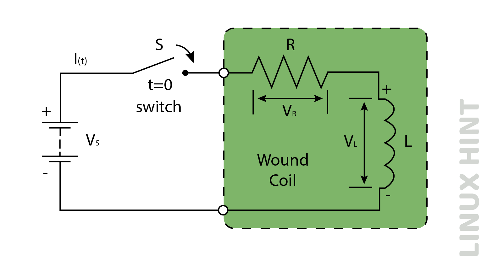
KVL is used to find the individual voltage of resistor and inductor:
![]()
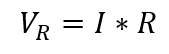
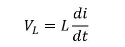
Where the voltage of resistor and inductor is given as:
The result obtained by putting VR and VL in the above equation:
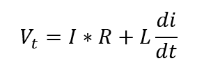
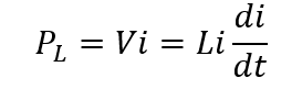
The voltage drop of resistance depends on the current, and for the inductor, it depends on the rate of change of current.
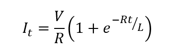
The formula of the current in the RL series circuit is given as:
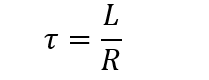
The time constant formula for the LR series circuit is given as:
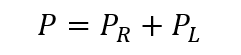
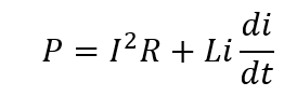
Power in the RL series circuit is given as:

Transient Characteristic Curve
The below given curve is the transient curve of an RL series circuit. The curve in the figure shows the voltage through the inductor. Initially, the voltage drop is maximum when the switch is at condition t = 0, but when the switch is closed, the voltage drop starts decreasing and reduces to zero after some time:
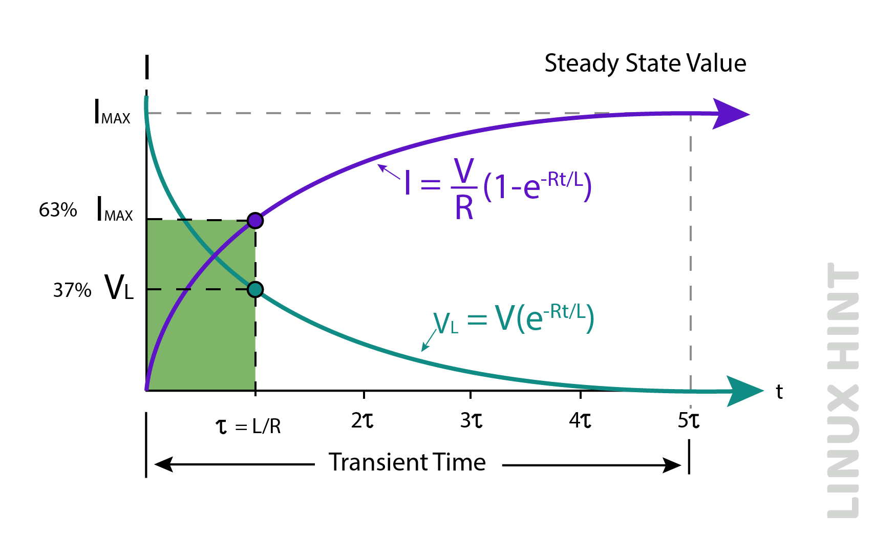
The x-axis shows the time constant T. When the value of the time constant T is 5T, then the voltage drop is fully zero. The time constant is directly related to the value of the inductor and inversely to the value of the resistance.
Example of RL Series Circuit
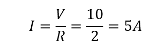
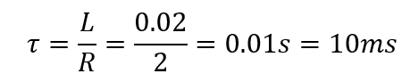
The value of the inductor is 20mH, and resistor in the RL series circuit is 2 ohm the dc voltage supply of 10V. find out the steady state current, time constant, transient time, and induced emf
Firstly, find the steady-state current:
Find out the time-constant:
Find the transient time:
![]()
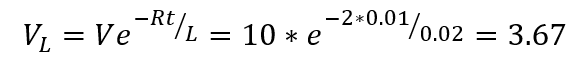
Now find the induced voltage after 50ms:
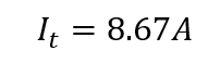
Lastly, find the instantaneous current:

Conclusion
The RL series circuit is also known as a filter. In the beginning, the inductor shows the maximum voltage drop, this drop reduces to zero after some time, this state may be known as the transient state.
Source: linuxhint.com