What is TX and RX on Arduino
-
- RX Receiver
- TX Transmitter
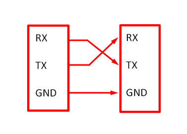
It’s important to consider that these RX and TX are specific to device itself means if you want to communicate between two Arduino the RX pin of first one will be connected to the TX pin of second one and similarly TX pin of first one with RX pin of second one:
Serial Interfaces have two modes: half and full duplex:
-
- Full duplex means you can send and receive data at same time
- Half duplex communication means that devices can either transmit or receive data at once
Serial Communication using RX/TX in Arduino
All Arduino boards have one or more serial ports known as UART (Universal Asynchronous Receiver & Transmitter). UART allows users to take inputs and output from the Arduino board so we can monitor our program. TX and RX pins classification on different boards are given here:
| BOARD | SERIAL PINS | SERIAL 1 PINS | SERIAL 2 PINS | SERIAL 3 PINS |
| Uno, Nano, Mini | 0 (RX),1(TX) | |||
| Mega | 0 (RX),1(TX) | 19(RX),18(TX) | 17(RX),16(TX) | 15 (RX),14(TX) |
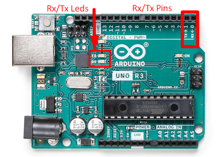
I have shown Serial pins RX and TX at pin location 0 and 1 respectively on the Arduino UNO board.
Note: In some older Arduino models like Mini, RX and TX pins are used for communication between your computer and board, which means if you connect any other external devices to these pins it can interfere with that communication, resulting in failing to upload your sketch over board. Some Arduino boards have separate ports for Serial communication with your computer and Serial1 communication port for any external device you want to connect that uses UART protocols.
TX/RX LEDs
TX and RX LEDs on the board flash when any kind of data is being transmitted or received using the USB serial port between your computer and Arduino board. Remember these LEDs don’t flash if serial communication is done through 0(RX),1(TX) pins on your board. These two pins are designated for connecting your own serial device whether the USB serial cable is connected or not. TX led blinking means the board is sending something via Serial.print() function.
UART Protocols Infrastructure Require for TX/RX
If you want to communicate with any external device than there are some requirements to be met to establish your connection via serial communication, now I will discuss some of those:
1: Required Pins – Overall UART infrastructure required two pins as discussed above RX/TX pins. RX for receiving & TX for transmitting.
2: Packet Structure – UART stands for (Universal Asynchronous Receiver & Transmitter) here the acronym A is important which stands for Asynchronous, UART is asynchronous communication because of no common clock sharing between devices. Both devices where serial communication is required must agree on the same structure at what data is being sent and at what speed the data is sent; this will help UART to sample the data and convert raw data into data packets.
3: Baud rate – Same data rate is a must for sharing data between two UART devices, both devices must be configured at the same data rate for sending and receiving. Common data rates used for TX/RX pins in Arduino includes 9600 & 115200 baud but some UARTS devices support higher data rates.
Conclusion
We have discussed most of the factors required for communication using TX/RX pins. Embedded systems and Arduino boards required serial communication between integrated circuits. These two pins have a significant use in establishing that communication.
Source: linuxhint.com