What Is the Difference Between Arduino Potentiometer and Rotary Encoder
Potentiometers and rotary encoders both are used to detect rotation or sense position. They are electromechanical devices used having diverse applications in the field of electronics. They can also be interfaced with Arduino for making different projects. This article is to demonstrate the fundamental differences between a potentiometer and a rotary encoder.
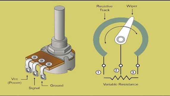
What is a Potentiometer
A potentiometer is a rheostat, or we can call it a variable resistor. The value of resistance varies according to the shaft rotation of the potentiometer. Potentiometers can only turn to a set distance. There are both analog and digital potentiometers, but they are almost similar. Analog potentiometers can be interfaced with microcontrollers on Arduino, Raspberry Pi, and other devices. A potentiometer possesses three pins that are input voltage pin Vcc, Ground Pin GND, and the input signal pin. The signal pin provides input to Arduino.
What is a Rotary Encoder
Rotary encoders sense the angular position of the rotary knob and send a signal to the microcontroller or any other device to which they are connected. It has a disc with evenly spaced contact areas that are connected to a common pin. Rotary encoders also have a built-in push button or rotary switch that gives ON and OFF signals according to specific requirements.
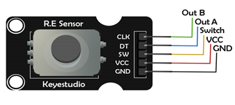
Pinout Diagram and Pin Description of Rotary Encoder
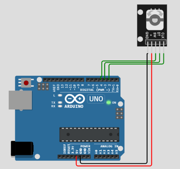
The diagram given below shows the pins of the rotary encoder. These pins are described as follows:
Out B or CLK
This pin gives an output of how many times the knob or rotary encoder has rotated. Each time when the knob is rotated, the CLK completes a cycle of HIGH and LOW. It is counted as one rotation.
Out A or DT
This is the second output pin of the rotary encoder that determines the direction of rotation. It lags 90° behind the CLK signal. Therefore, if its state is not equal to CLK’s state then the direction of rotation is clockwise, otherwise, anti-clockwise.
Switch
The switch pin is used to check if the push button is pressed or not.
Vcc
This pin is connected to a 5V supply
GND
This pin is connected to the Ground
Difference Between Potentiometer and Rotary Encoder
| Specification | Potentiometer | Rotary Encoder |
| Rotation | The potentiometer can be rotated only in one direction, and that too for three-fourths of a circle. | The Rotary Encoder is capable of rotating 360° continuously in both clockwise and anticlockwise directions. |
| Analog or Digital Device | The potentiometer is mostly an analog input device that measures the change in position through a change in the value of a resistor | A rotary encoder is a digital input device that senses the angular position and provides digital values.
|
| Number of Input Positions | A potentiometer has an infinite number of input positions on which values can be taken because it is an analog device | Rotary encoders have a finite number of input positions. |
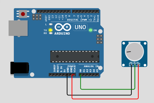
Setting Up Potentiometer with Arduino
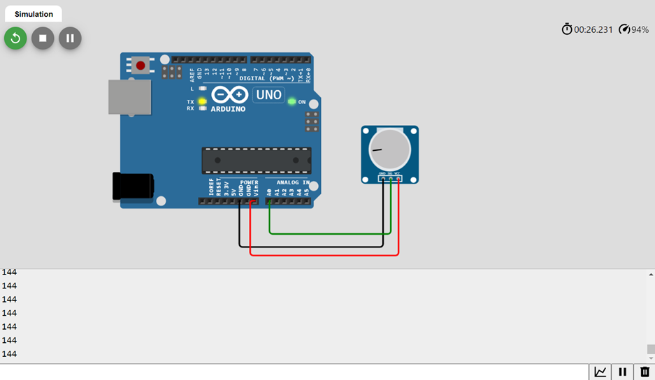
The potentiometer is easier to set up with an Arduino than a rotary encoder. The potentiometer has only three pins VCC, GND, and an INPUT pin that is connected to Arduino. Interfacing of the potentiometer with Arduino is shown below:
Programming the potentiometer in Arduino is easier than that of the rotary encoder. Given below are the sample syntax codes for both of them.
Sample Code for Potentiometer
void setup() {
pinMode(pot, INPUT); //Setup value taken from potentiometer as input
Serial.begin(9600);
}
void loop() {
int potValue = analogRead(pot); //Read value of input taken by potentiometer
map(potValue, 0, 1023, 0, 255); //Scaling the value of input to match 8-bit
Serial.println(potValue); // Prints value that was input to potentiometer
delay(100);
}
The potentiometer code is very easy and simple. The analog input pin of Arduino is simply declared to take input from the potentiometer, and then analogRead() and map() functions are used to read and give the exact value of reading from the potentiometer.
Interfacing Rotary Encoder with Arduino
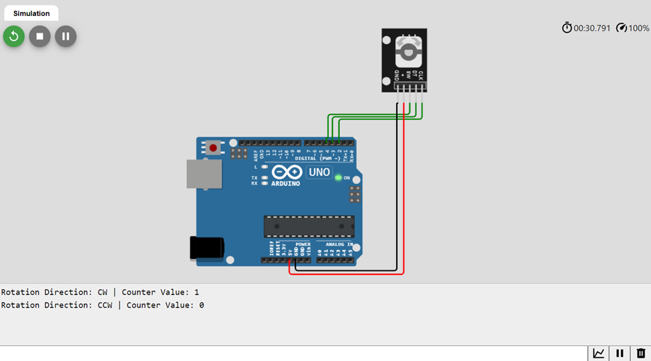
The rotary encoder has five pins. VCC and GND of the rotary encoder are connected to that of Arduino. The remaining pins CLK, DT, and SW are connected to the digital input pins of Arduino.
Arduino Code for Rotary Encoder
#define CLK_PIN 2
#define DT_PIN 3
#define SW_PIN 4
int counter = 0;
int currentCLKState;
int lastCLKState;
String currentDirection ="";
unsigned long lastButtonPressTime = 0;
void setup() {
// Set encoder pins as inputs
pinMode(CLK_PIN, INPUT);
pinMode(DT_PIN, INPUT);
pinMode(SW_PIN, INPUT_PULLUP);
// Setup Serial Monitor
Serial.begin(9600);
// Read the initial state of CLK
lastCLKState = digitalRead(CLK_PIN);
}
void loop() {
// Read the current state of CLK
currentCLKState = digitalRead(CLK_PIN);
// If last and current state of CLK are different, then a pulse occurred
// React to only 1 state change to avoid double count
if (currentCLKState != lastCLKState && currentCLKState == 1) {
// If the DT state is different than the CLK state, then
// the encoder is rotating counter-clockwise, so decrement
if (digitalRead(DT_PIN) != currentCLKState) {
counter--;
currentDirection = "CCW";
} else {
// Encoder is rotating clockwise, so increment
counter++;
currentDirection = "CW";
}
Serial.print("Rotation Direction: ");
Serial.print(currentDirection);
Serial.print(" | Counter Value: ");
Serial.println(counter);
}
// Remember the last CLK state
lastCLKState = currentCLKState;
// Read the button state
int buttonState = digitalRead(SW_PIN);
// If we detect a LOW signal, the button is pressed
if (buttonState == LOW) {
// If 50ms have passed since the last LOW pulse, it means that the
// button has been pressed, released, and pressed again
if (millis() - lastButtonPressTime > 50) {
Serial.println("Button Pressed!");
}
// Remember the last button press event time
lastButtonPressTime = millis();
}
// Put in a slight delay to help debounce the reading
delay(1);
}
In the above-given code, the state of the CLK pin is checked in the loop() function. If it is not equal to its previous state, it shows that the rotary knob has rotated. Now, to check the direction of knob rotation, the present state of CLK is compared with the state of DT. If both states are unequal, it shows that the knob has rotated clockwise and counter increments its value to show the position of the rotary knob. In the opposite case, counter decrements.
Applications
Potentiometers are mainly used where a control function is required. They are used in volume control, LED brightness control. On the other hand, Rotary encoders offer a wide range of applications. They are used in robotics, medical equipment, automation, and gaming.
Conclusion
Potentiometers and rotary encoders are both particularly useful devices in the field of electronics. Rotary encoders are advanced as compared to potentiometers, as they can rotate continuously to 360°. Similarly, they have more applications in modern electronics, and they are slightly more difficult to use than potentiometers.
Source: linuxhint.com