What is Passive Low Pass Filter – Passive RC Filter
This tutorial will be a brief discussion about low pass filters, their construction, frequency response, cut-off frequency, calculation of output voltage, higher order low pass filter, and their applications.
What Is a Filter?
A filter is a circuit used in digital electronics that is designed to pass certain signals and block others. These filters may be designed by using active elements or passive elements. Active elements include transistors, Operational Amplifiers, and Field Effect Transistors whereas passive components include resistors, capacitors, and inductors.
Types of Filters
Filters are mainly classified into two types:
Active Filters: These filters use active elements and are used as amplification devices and strengthen signals.
Passive Filters: These Filters use passive elements and are designed to allow certain signals of high or low frequencies depending on their usage.
This tutorial will be covering the simplest passive low-pass filter that consists of a capacitor and a resistor.
The Passive RC Low Pass Filter
A Passive RC Low Pass Filter is a combination of capacitance and resistance that is designed to filter or attenuate high frequencies and allow only those frequencies that fall below the cut-off frequency.
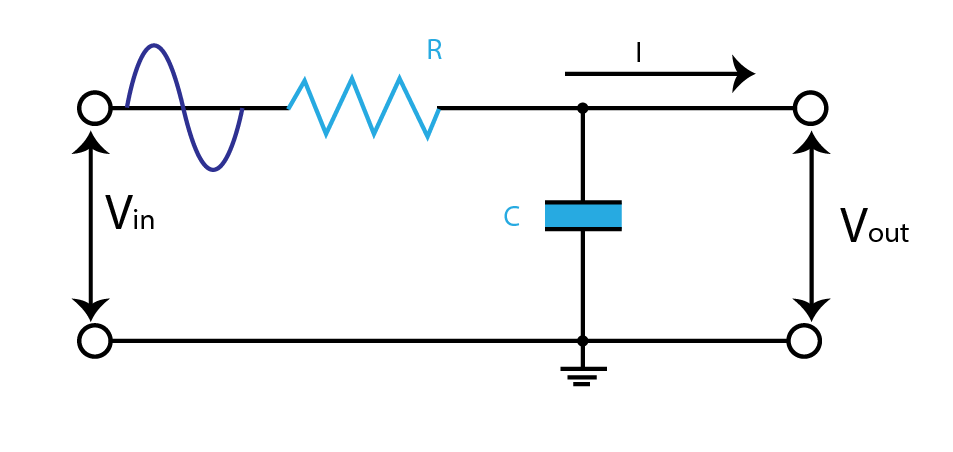
From the above circuit diagram, it is clear that a low pass filter is made by connecting a resistor ‘R’ in series with Capacitor ‘C’. The resistor is not dependent upon incoming frequencies, whereas the Capacitor is sensitive to changes in input frequencies. Therefore, the output voltage is taken across the capacitor.
A capacitor is the only reactive component in the circuit, so it is also called a first-order circuit.
The capacitor opposes the change in current. Therefore, when the input signal changes, the capacitor’s reactance also changes. We can say that when a capacitor is charged its voltage potential is very high, but the voltage drop is very low, but when the capacitor is charging voltage potential is low, but the voltage drop is high. The resistor is independent of the change in input. So, the capacitor lets this circuit behave as a voltage frequency divider.
The Cut-Off Frequency
The Cut-Off Frequency is the frequency at the point where capacitive reactance becomes equal to resistance. At this instant, the output signal is attenuated 3dB of the input.
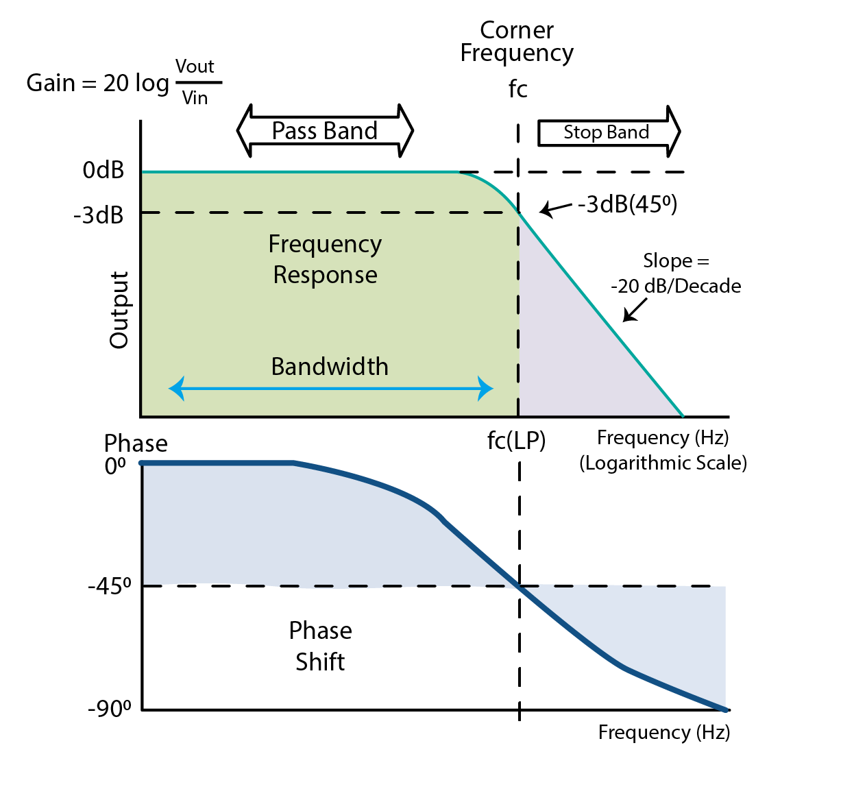
Due to the presence of a capacitor in the filter, the phase angle of the input signal leads to the phase angle of the output signal and is 45° ahead of it. This is because a capacitor takes some time to charge. The value of the cut-off frequency and phase angle for the low pass filter can be calculated through the following equations:

Output Voltage Calculation in Low Pass Filter
VDR (Voltage Divider Rule) is applied to the circuit to calculate the output voltage across the capacitor.

Where XC is the reactance of the Capacitor and Z is the total impedance of the resistor and capacitor.
Frequency Response of a Low Pass Filter
The graph below shows how certain frequencies are allowed through a low pass filter while others are declined. The frequencies up to critical frequencies are allowed and they are called pass bands. This passband determines the bandwidth of the low pass filter. The rate at which higher frequencies are attenuated is calculated through the gain of the filter given by:

Time Constant
We have studied above that the output signal lags behind the input signal due to a delay in capacitor charging. The time taken by the capacitor to charge up to 63% of its total value is called a time constant that is related to frequency:

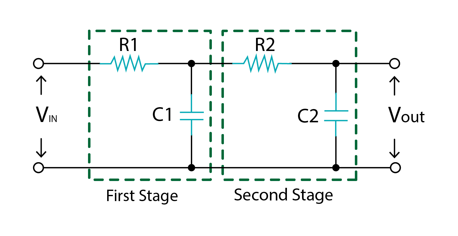
Second Order Passive Low Pass Filter
Second or higher-order Passive Low Pass Filters are formed by cascading RC networks. Similarly, any nth-order filter can be designed. Second-order low-pass filters are very useful in several other digital circuits, such as designing noninverting amplifiers.
Applications of Low Pass Filter
Low Pass Filter is generally used in several different electronic circuits to eliminate noise signals, as rectifiers to eliminate AC ripples, audio receivers, audio equalizers, oscilloscope, function generator, bass frequency modulation, and demodulation and integrators.
Conclusion
A Low Pass RC filter is made through passive elements such as resistors and capacitors. Inductors may also be included if required. This kind of filter allows low frequencies to pass that lie below the cut-off frequency and blocks high-frequency signals. For this purpose, the capacitor is used as its charging and discharging phenomenon makes the circuit voltage divider and desired signals can be obtained across the capacitor. These are mainly used to filter noise.
Source: linuxhint.com