Understanding Logic NOT Gate – A Complete Tutorial
What is Logic NOT Gate?
In Digital Electronics, NOT Gate is the most fundamental gate. It consists of one input that corresponds to one output. It performs the function of inversion. When input is HIGH, the output goes LOW, whereas when input is LOW, the output is HIGH.
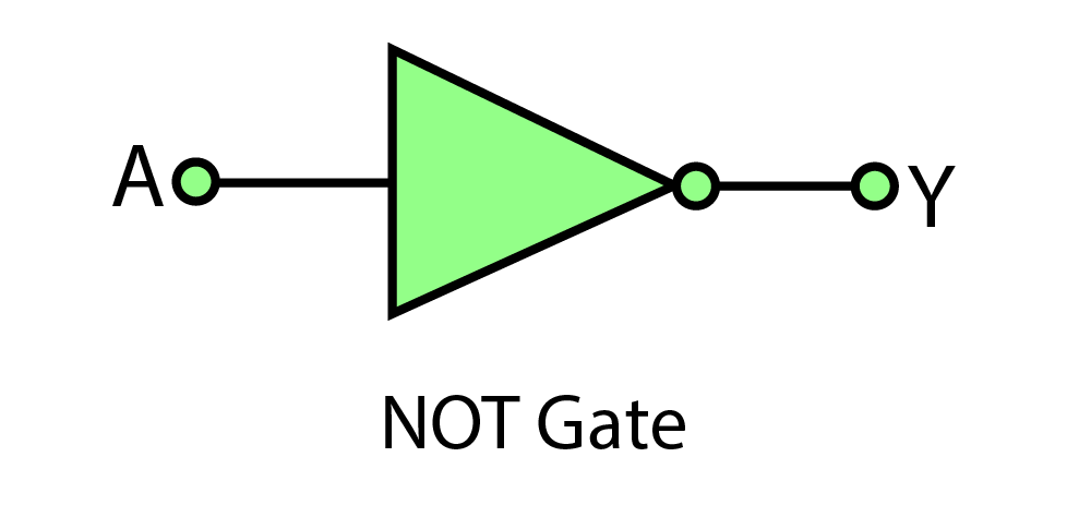
Symbol of Logic NOT Gate and its Boolean Expression
The symbol allotted to Logic NOT Gate by IEEE (Institute of Electrical and Electronics Engineers) consists of a triangle that points towards the right. At the right-pointing corner of the triangle is an inversion bubble, which shows that the output is inverted. This inversion bubble is also used in NAND and NOR Gates. Furthermore, when this inversion bubble is used at the input side, it indicates a low input.
The Boolean Expression for Logic NOT Gate is given as shown below:

Truth Table of Logic NOT Gate
The truth table of Logic NOT gate shows the states of inputs and their respective outputs.
| Input | Output |
|---|---|
| 0 | 1 |
| 1 | 0 |
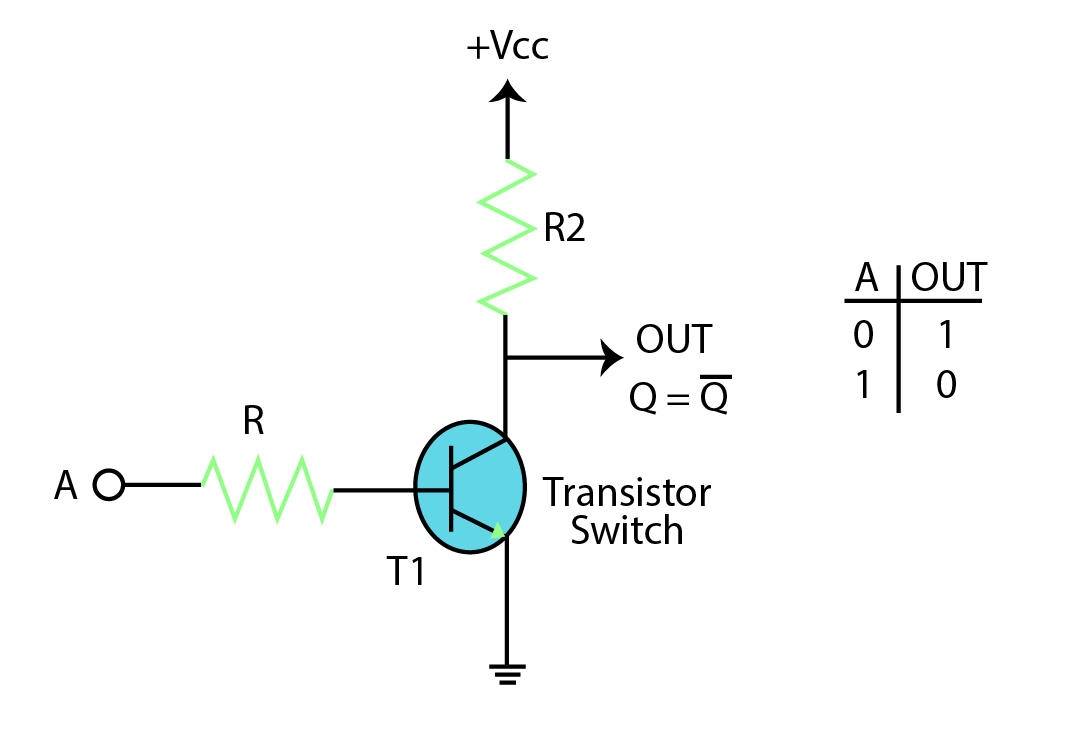
Construction of Logic NOT Gate
A simple Logic NOT Gate can be built by using a transistor as a switch. For this purpose, the input is directly fed into the base of the transistor through a resistive path. When there is no input applied at the base, a small saturation current flows through the collector, which gives HIGH output. However, when input is applied at the base, all the transistor acts as a closed switch and all current flows through the transistor, and the output at Q is LOW.
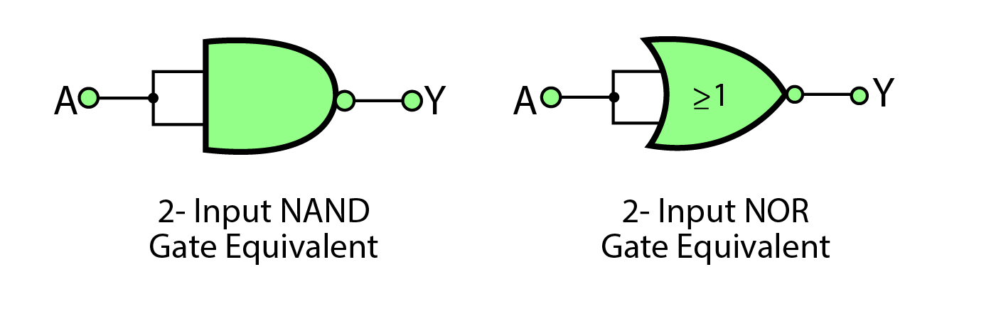
Gates That Work as Equivalent for NOT Gate
Along with transistors being used as NOT Gate, NAND and NOR Gates can also be used as NOT Gate by combining their two inputs into one.
Truth Table of 2 Input NAND Gate Equivalent to NOT Gate
| A | A | Y= (A.A)’=A’ |
|---|---|---|
| 0 | 0 | 1 |
| 1 | 1 | 0 |
Truth Table of 2 Input NOR Gate Equivalent to NOT Gate
| A | A | Y= (A+A)’=A’ |
|---|---|---|
| 0 | 0 | 1 |
| 1 | 1 | 0 |
Applications of Logic NOT Gate
Logic NOT Gate has multiple applications in the field of digital electronics, as explained below:
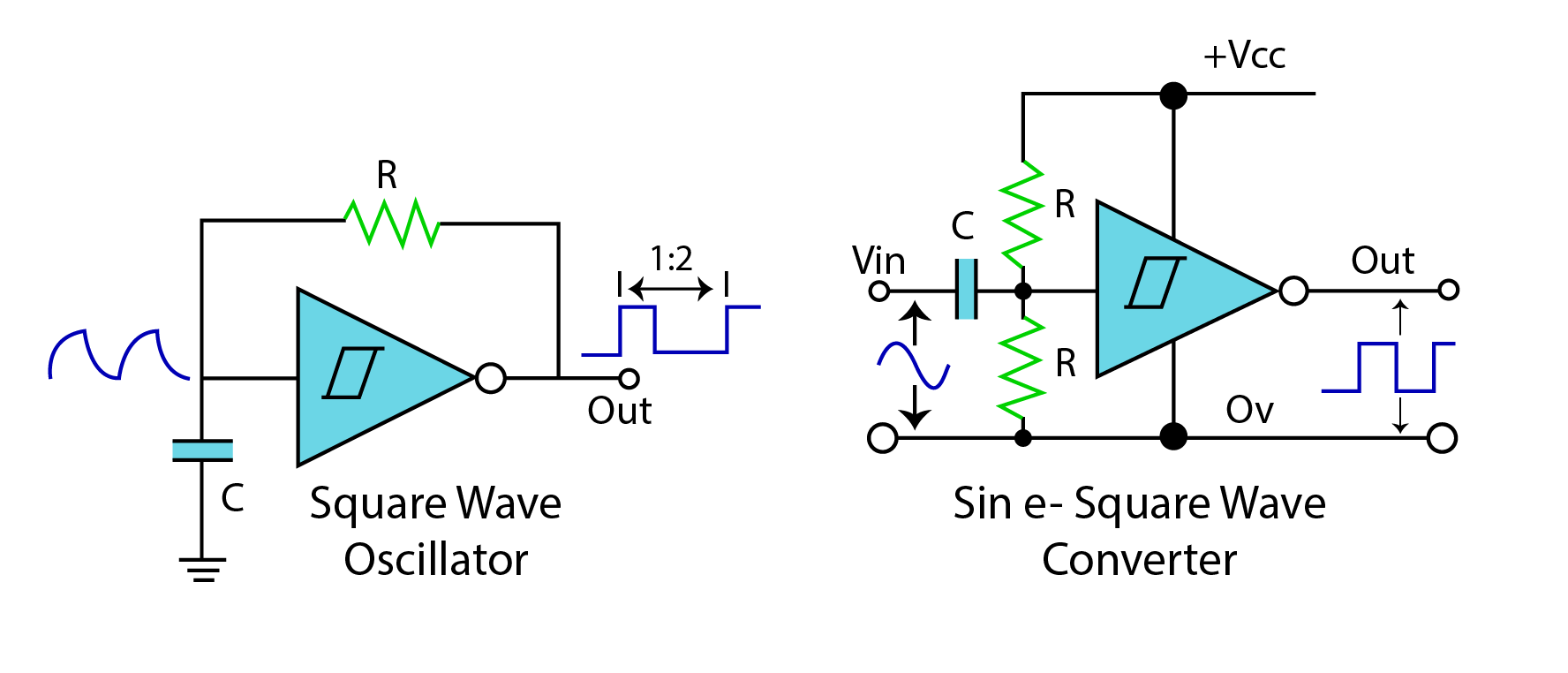
1. Schmitt NOT Gate Inverter Oscillator
Schmitt NOT Gate Inverter Oscillator is used to generate a square waveform. The circuit given below shows that when Capacitor C is initially discharged the input to the inverter is LOW resulting in a HIGH output through Schmitt Inverter.
When the output is fed back to the inverter’s input through resistor R then Capacitor C begins to charge. When the Capacitor is almost charged, the input of the inverter changes to HIGH, and the output changes to LOW. The same process repeats again and again, and a square waveform is generated whose duty cycle is 33%
2. Street Lights Switching using Light Dependent Resistor (LDR)
Logic NOT Gate can also be used in streetlights using Light Dependent Resistors (LDRs). When in Daylight, light falls on the resistor, its resistance decreases and current starts flowing through the transistor and the output is LOW which means that at daytime Street Light is OFF. At night, the resistance of LDR increases, and Output is HIGH due to leakage collector current, and Street Light turns ON.
3. 7404 Logic NOT Gate or Inverter
This is the most readily available IC consisting of six NOT Gates that are used in multiple digital circuits such as signal inversion, level shifting, and logic signal buffering.
Conclusion
Logic NOT Gate is the most important gate in digital electronics. Along with AND, and OR Gates it is responsible for making other gates such as NAND, and NOR. It has diverse applications in day-to-day electronics. It can be said that without Logic NOT Gate field of electronics is incomplete.
Source: linuxhint.com