Understanding Class AB Amplifier Design and Class AB Biasing
Need of Class AB Amplifier
The class of amplifier first designed was class A amplifier and then class B amplifiers were designed. However, due to some limitations of both classes a third class, known as class AB amplifier, was designed.
Limitation of Class A Amplifier
Class A amplifiers use an NPN transistor to amplify the input signal, but they are only 50% efficient. This is because they always operate in active regions due to biasing voltage even if the input signal is not applied. Therefore, DC current flows through the amplifier even in OFF mode. This causes extra power dissipation in the form of heat loss. The good quality of a class A amplifier is that there is no distortion in the output signal because it always operates in the active region.
Limitation of Class B Amplifier
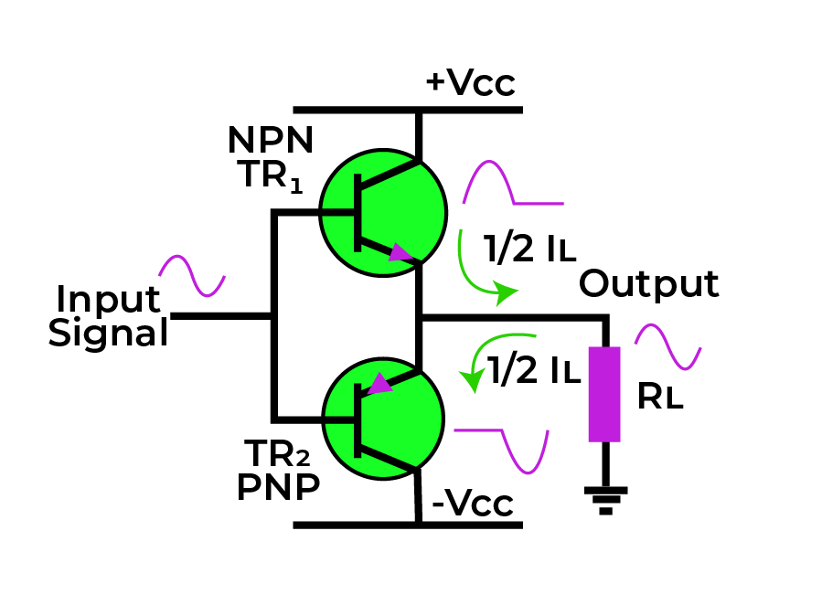
To overcome the power loss in class A amplifiers, class B amplifiers were introduced. Class B amplifiers use two transistors that conduct in alternative half-cycles. This increased the efficiency of the amplifier to 78.5%. However, during the zero crossing of the input signal when one transistor turns ON and the other turns OFF, a cross-over distortion was observed. This happened in the short time period when both transistors were not conducting.
These limitations of class A and class B amplifiers led to the development of class AB amplifiers.
Design of Class AB Amplifier
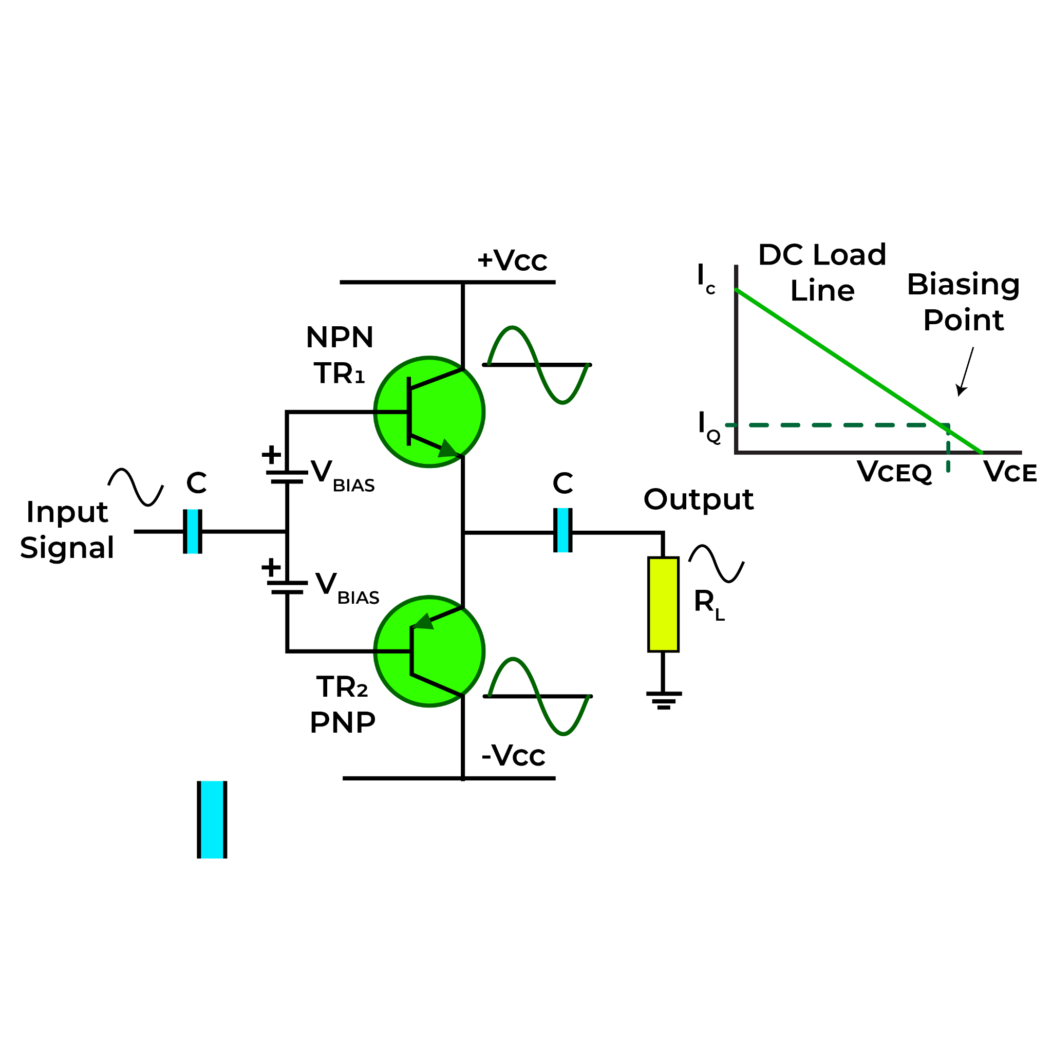
Class AB amplifiers are designed to overcome the ineffectiveness of amplifiers belonging to class A and distortion at zero crossing of amplifiers belonging to class B. It consists of two transistors, one in NPN and the other in PNP. The difference is created in biasing of class AB amplifiers. The biasing point of a class AB amplifier is set slightly above the cut-off region. This helps to overcome the cross-over distortion during zero crossing of the input signal. The biasing voltage makes the transistors conduct even when the input signal is removed. The figure given below shows the circuit diagram of class AB amplifiers.
Q point of Class AB Amplifier
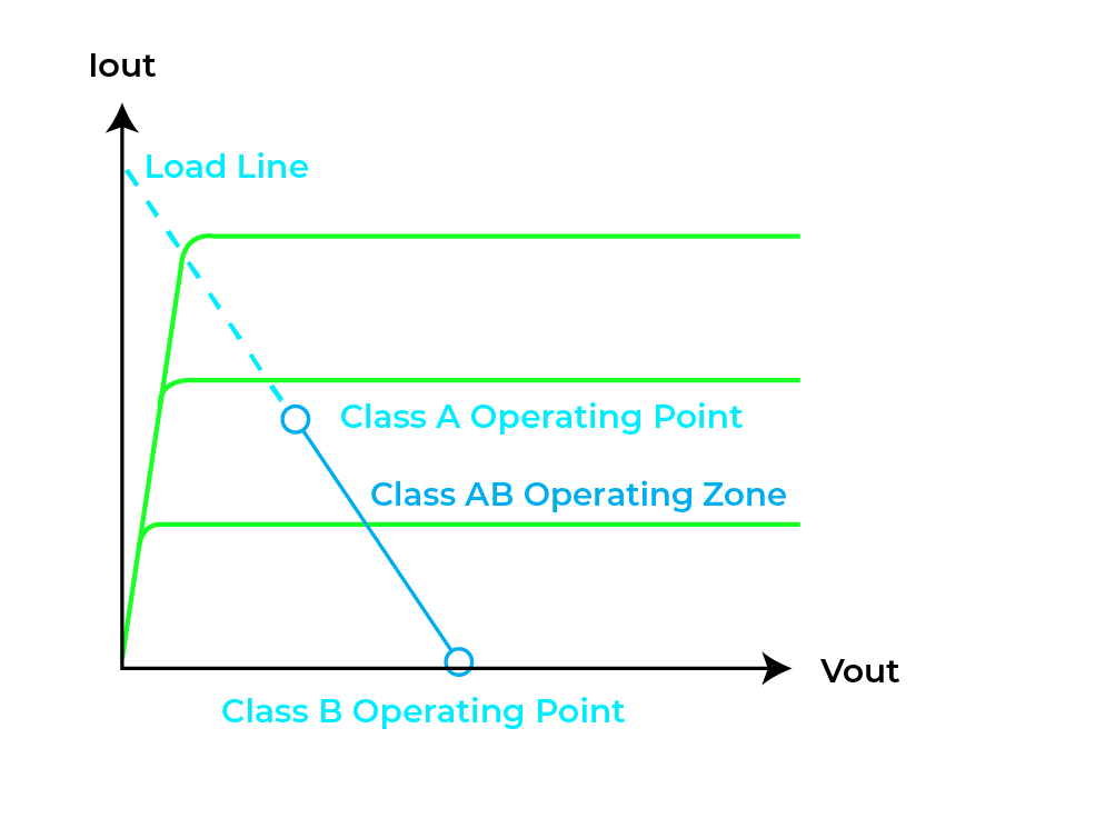
Q point is the point of operation of any amplifier. The Q-point of a class AB amplifier lies slightly above the cut-off region on the DC load line of the amplifier. The Q point of class A amplifiers lies in the active region that makes them inefficient, whereas that of class B is in the cut-off region that causes cross-over distortions. Therefore, the Q-point of the class AB amplifier is set in between the Q-points of amplifiers of the A and B classes. This can be witnessed in the diagram below.
Conduction Angle of Class AB Amplifier
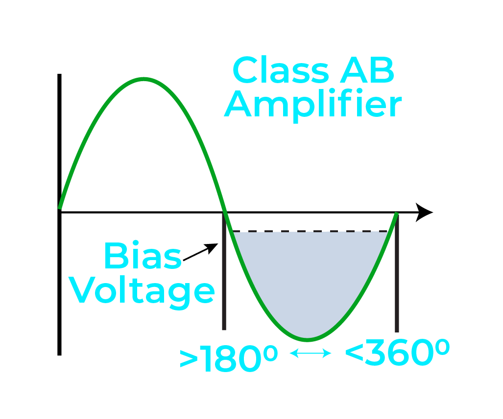
The conduction angle tells about the activity of an amplifier. It indicates the angles during which the amplifier is turned ON. For the class AB amplifiers, the conduction angle lies between 180° to 360° of the input cycle.
Biasing of Class AB Amplifier
Class AB amplifiers can be biased in three different ways that are mentioned and explained below:
- Voltage Biasing
- Resistor Biasing
- Diode Biasing
Voltage Biasing
This is the simplest method of biasing a class AB amplifier. In this method, the bases of NPN and PNP transistors are independently biased with separate batteries or DC generators. However, this method cannot be implemented due to unbearable cost and packaging constraints.
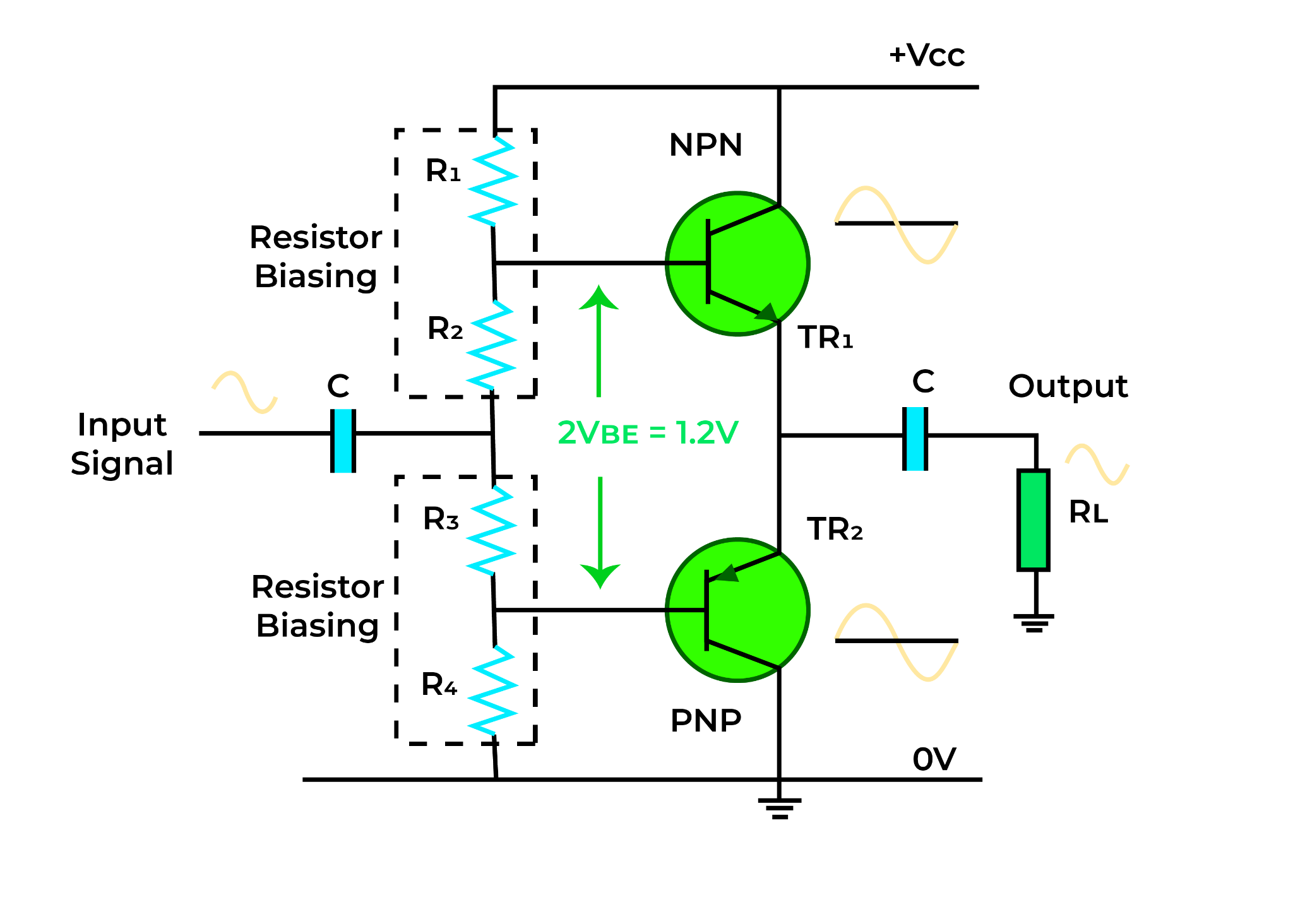
Resistor Biasing
In resistor biasing, four resistors are connected across the input voltage to create a voltage divider network. The resistors R1 and R4 in the voltage divider network are used to set the Q-point slightly above the cut-off area, and values of R2 and R3 are chosen such that the voltage drop across them is enough to turn the transistors completely ON. The main advantage of this biasing is the ease of changing the values of resistors as per requirement. However, if the value of resistance changes due to temperature fluctuations, it can change the Q-point of a class AB amplifier.
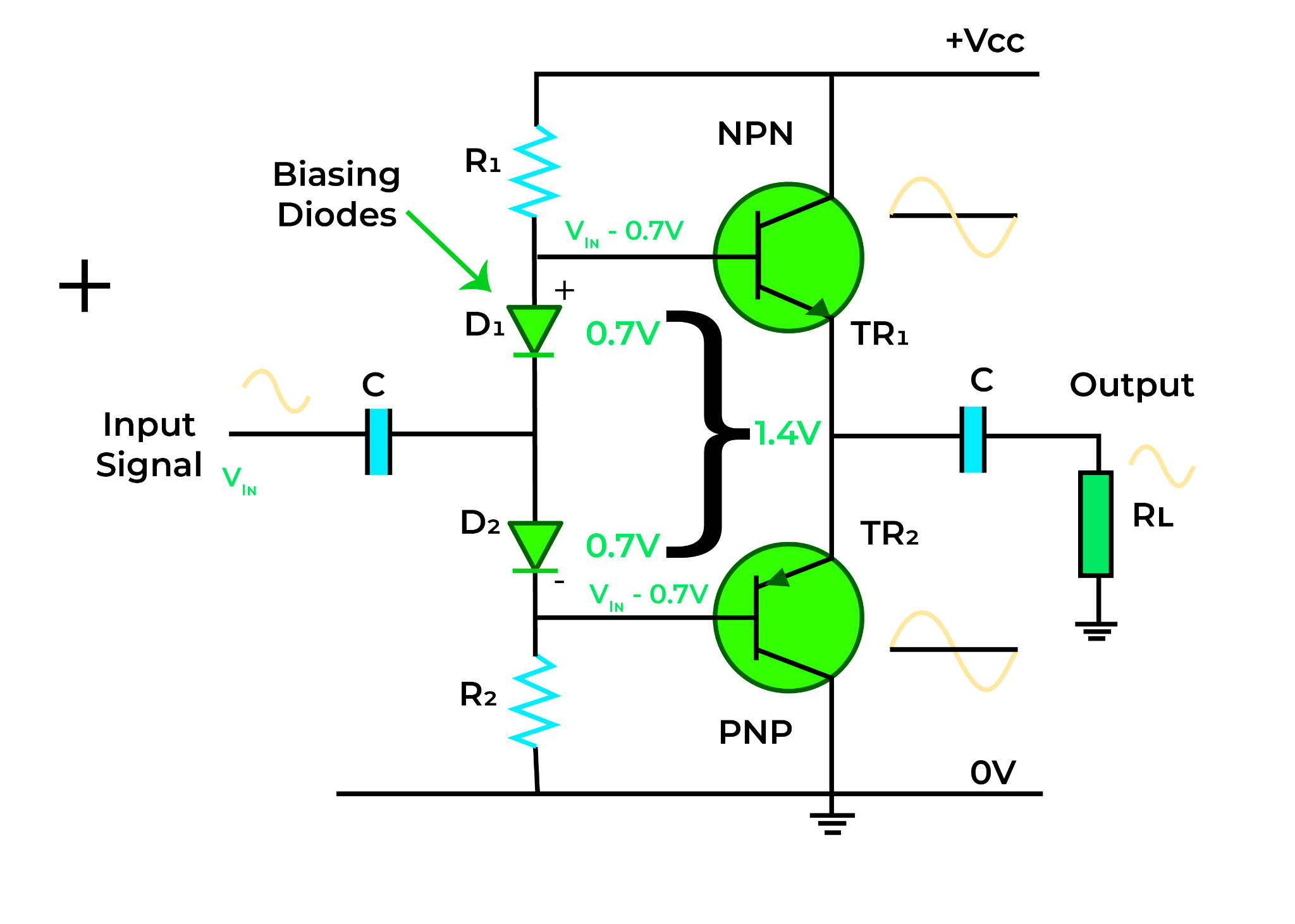
Diode Biasing
To solve the problem of temperature fluctuations in resistor biasing, diode biasing is used. Diodes can give a constant voltage of 0.7V. Therefore, two diodes D1 and D2 are connected in place of R2 and R3. When current flows through D1 and D2 they give a combined voltage drop of 1.4V that is enough to turn the transistors fully ON.
Comparison of Different Amplifier Classes
The basic comparison among the three major classes of Amplifiers is given below.
- Class A Amplifier
There is only one output transistor in Class A amplifiers that conducts for the whole 360° of the input cycle.
- Class B Amplifier
There are two output transistors in Class B amplifiers that conduct for one-half that is 180° of the input cycle.
- Class AB Amplifier
There are two output transistors in Class AB amplifiers that conduct somewhere between 180° to 360° of the input cycle.
Advantages of Class AB Amplifier
Class AB amplifiers unite the benefits or plus points of amplifiers of class A and B. These include:
- The cross-over distortion of the class B amplifier is eliminated.
- It has highly efficient in amplification
- Class AB amplifiers are linear amplifiers because their output signal is in phase with the input signal.
Disadvantages of Class AB Amplifier
Although class AB amplifiers have overcome the disadvantages of class A and class B amplifiers, they have some disadvantages that include:
- They are very expensive amplifiers.
- Designing a Class AB amplifier is a bit more complicated than designing Class A and Class B amplifiers.
- If biasing is not accurately done, it can cause spikes or distortions in the output signal.
Applications of Class AB Amplifier
Class AB amplifiers are widely used in electronic devices of daily usage. They are used as audio amplifiers in televisions and radio receivers. They are also used in satellite and wireless communication systems. As power amplifiers, they are used in RF transmitters, speakers, and headphones.
Conclusion
Class AB of amplifiers is very beneficial as it overcomes the flaws of amplifiers of class A and B. Class AB of amplifiers is designed in such a way that it is highly efficient and has no cross-over distortion. These amplifiers are widely used in day-to-day electronic gadgets, as well as in satellite communication.
Source: linuxhint.com