Push Button with ESP32 – Arduino IDE
ESP32 is an IoT board that can be interfaced with different external peripherals to generate outputs. ESP32 takes input from devices like push buttons and generates responses according to the received input. Push buttons can be used to control multiple sensors and devices like controlling a LED or maintaining speed of motors. Here in this lesson, we will discuss push button interfacing with ESP32.
Following is the table of content for this lesson:
1: Introduction to Push Button
2.1: Push Button Working Modes
3: Interfacing Push Button with ESP32
3.1: Digital Input Output Pins in ESP32
3.2: How to Read Digital Inputs in ESP32
3.3: Interfacing Push Button with ESP32 Using Digital Read Function
3.6: Code for Interfacing ESP32 with Push Button
1: Introduction to Push Button
A push button is a simple button with a mechanism to control states of different machines or processes. Push button is made up of hard material like plastic or metal and the top surface is usually flat which allows users to press it.
In ESP32 projects the push button is widely used to control input and output states of the pin. Toggle switches and push buttons operate on slightly different principles. Conventional or toggle switch comes to rest once it is pressed while the push button is a two-position device which usually comes to rest once it is released.
Let’s get deep into the working principle of Push button in details:
2: Working of Push Button
A push button normally has 4 pins. These 4 pins are connected in the form of a pair such as two upper pins are internally connected similarly the other two are also internally connected.
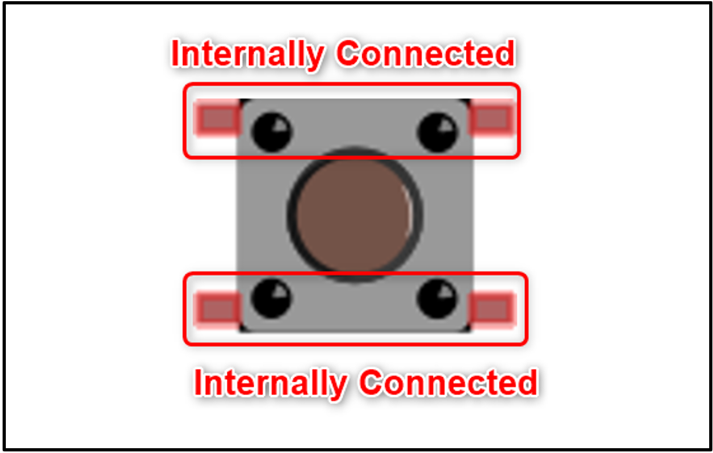
To know which two pins are connected, take a multimeter (DMM) and set it to continuity test, now attach the positive probe with any leg of the button and then one by one attach the negative probe of the multimeter with other legs. If the connection is complete between both ends beep sound can be heard from the multimeter. Those two legs which are internally connected will complete the circuit.
2.1: Push Button Working Modes
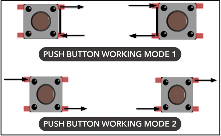
To use the push button in a circuit we need one pin from each internally connected pair. If we take the pins of the push button from the same pair which are internally connected will result in a short circuit as these are already connected it will bypass the push button mechanism.
Based on this mechanism push button can work in following two modes:
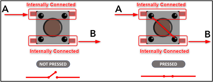
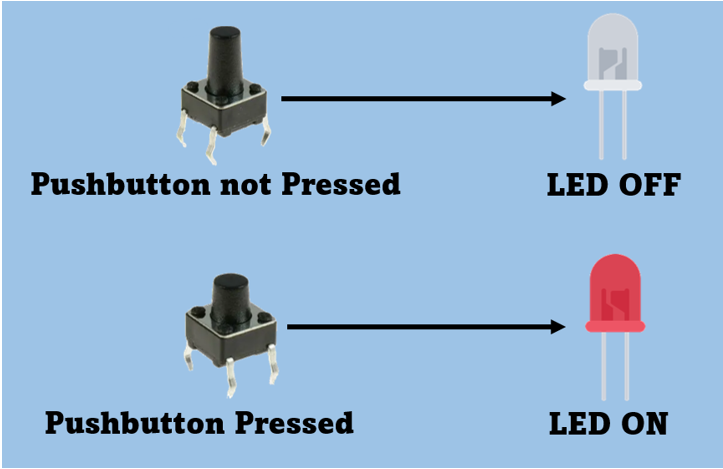
If we take an example of the mode shown in the image below. We can see that when the button is not pressed the internal connection is open once the button is pressed the internal A and B terminal will be connected and the circuit will complete.
Now we have completed the basic principle behind the working of push buttons. Next we will interface a simple push button with ESP32 and control a LED using it.
3: Interfacing Push Button with ESP32
Before interfacing the push button with ESP32 one must know the GPIO pins that can be used as an input. Now we will discuss the digital input output pins in ESP32.
3.1: Digital Input Output Pins in ESP32
ESP32 has a total of 48 pins each of which is specific for a certain function, among the 48 pins some are not physically exposed which means we cannot use them for external purposes. These pins are integrated inside ESP32 for different functions.
ESP32 board has 2 different variants having 36 pins and 30 pins. Here the difference of 6 pins between both boards lies because of 6 integrated SPI flash pins available for SPI communication on a 36 pins variant of ESP32 board. However, these 6 SPI pins cannot be used for other purposes such as input output.
The below given pinout is of 30 pin ESP32 board:
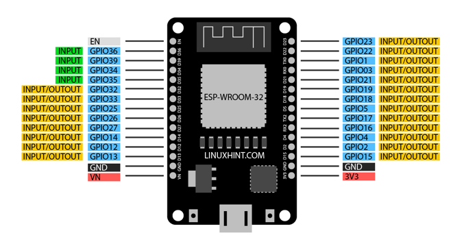
Among all the GPIO only 4 pins (34, 35, 36 and 39) are input only while all other pins can be used for both input and output. As mentioned above the 6 SPI pins cannot be used for input or output.
3.2: How to Read Digital Inputs in ESP32
Push button input can be read on a defined GPIO pin for which a function pinMode() needs to be defined first inside the Arduino code. This function will set the GPIO pin as input. pinMode() Function syntax is as follows:
To read data from a defined GPIO pin digitalRead() function will be called. Following is the command one can use to take data from push button on a GPIO pin:
3.3: Interfacing Push Button with ESP32 Using Digital Read Function
Now we will interface ESP32 with pushbutton using the digital read function at any GPIO pin. Taking the input from the pushbutton a LED will be turned ON or OFF.
3.4: Hardware Required
Below is the list of required components:
-
- ESP32 Board
- A LED
- 220 Ohm resistors
- 4 Pin Push Button
- Breadboard
- Connecting Jumper wires
3.5: Schematic
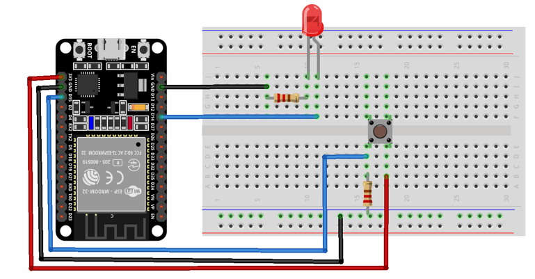
Below image is the schematic diagram of the push button with ESP32. Here input is read from the push button at GPIO pin 15, and LED is connected at GPIO pin 14.
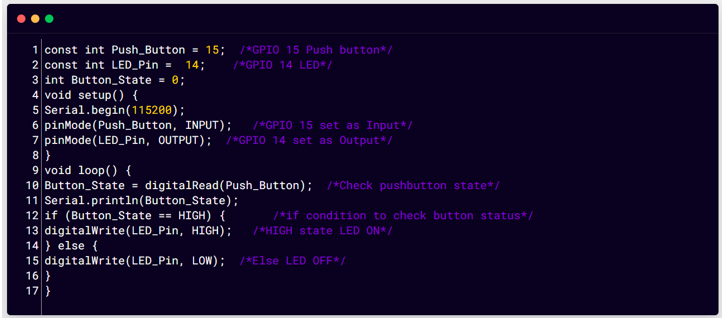
3.6: Code for Interfacing Push Button with ESP32
Now to upload code to ESP32 Arduino IDE editor will be used. Open the IDE and connect the ESP32 board after that select the COM port from the tool section. Once the ESP32 board is ready paste the code in IDE and click upload:
const int LED_Pin = 14; /*Digital pin 14 defined for LED*/
int Button_State = 0;
void setup() {
Serial.begin(115200);
pinMode(Push_Button, INPUT); /*GPIO 15 set as Input*/
pinMode(LED_Pin, OUTPUT); /*GPIO 14 set as Output*/
}
void loop() {
Button_State = digitalRead(Push_Button); /*Check pushbutton state*/
Serial.println(Button_State);
if (Button_State == HIGH) { /*if condition to check button status*/
digitalWrite(LED_Pin, HIGH); /*HIGH state LED ON*/
} else {
digitalWrite(LED_Pin, LOW); /*Else LED OFF*/
}
}
Code started by defining GPIO pins for LED and pushbutton. After that LED GPIO is declared as output while push button GPIO is set as input.
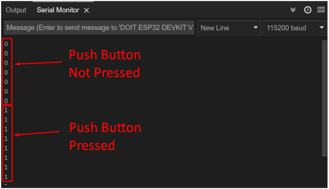
In the end push button state checked using the if condition. Push button state is also printed on serial monitor using Serial.println(Button_State).
If the push button input is HIGH led it will turn ON else, it will remain OFF.
3.7: Output
At first, we can see the LED is OFF.
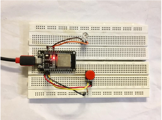
Now press the push button a HIGH signal will be sent to ESP32 GPIO 15 and the LED will turn ON.
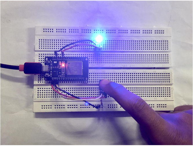
Same output can also be seen on the Arduino serial monitor.
Conclusion
ESP32 has multiple GPIO pins that can read digital data from sensors like push buttons. Using the digital read function push button can be easily interfaced with ESP32 to control different devices. Using this article once can interface the push button with any GPIO pin of ESP32.
Source: linuxhint.com