PIR Sensor HC-SR501 Arduino Nano Tutorial – Step by Step Instruction
Introduction to PIR Motion Sensor (HC-SR501)
A PIR motion sensor, also known as a Passive Infrared Sensor, is a type of electronic device that is commonly used to detect the presence of a human or animal within a certain range. The HC-SR501 is a popular model of PIR motion sensor that is known for its reliability and ease of use.
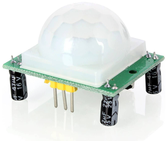
It works by using a passive infrared detector to sense changes in temperature, which can be caused by the movement of a person or animal. If the object movement is detected, a signal is sent to devices such as a security system or a lighting control panel. PIR motion sensors are often used in home security systems, automated lighting systems, and other applications where it is important to detect the presence of a person or animal.
Working of PIR Motion Sensor (HC-SR501)
The HC-SR501 PIR motion sensor works by using a passive infrared detector to sense changes in temperature. It is designed to detect the presence of a human or animal within a certain range, typically up to about 8 meters (26 feet).
When the sensor is idle, it is constantly monitoring the temperature in its field of view. If the sensor detects a change in temperature, such as would be caused by the movement of a person or animal, it will send a signal to a connected device. Using this signal, we can generate responses such as turning ON a light or activating an alarm.
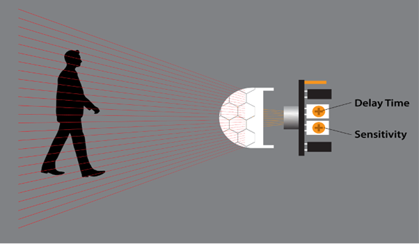
The PIR motion sensor has two potentiometers on board that can be used to adjust the sensitivity and Time delay of the sensor.
- Sensitivity determines how much of a temperature change is needed to trigger a PIR sensor. It can be set depending upon motion we need to detect such as mouse or leaf movement.
- Time delay determines how long the sensor remains active after detecting a change in temperature.
Pinout HC-SR501
PIR sensor pin includes:
- VCC: This is the power pin of the PIR sensor. Connect it to a 5V power source.
- GND: This is the ground pin. Connect it to the GND or negative terminal of the power source.
- OUT: This is the output pin. It sends a digital signal to a connected device when the sensor detects movement.
- Adjust Delay: This is the sensitivity adjustment pin. Using this sensitivity of the sensor can be adjusted.
- Adjust Sensitivity: This is the time delay adjustment pin. It can be used to adjust the length of time that the sensor remains active after detecting a change in temperature.
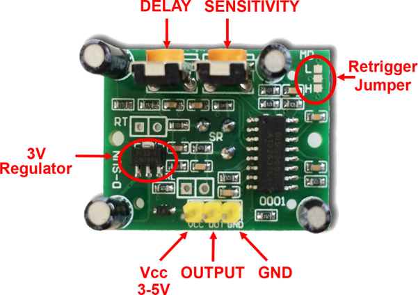
PIR HC-SR501 has 3 output pins. Two pins VCC and GND are power pins while the middle or third pin is for output digital trigger signal.
Interfacing PIR Motion Sensor (HC-SR501) With Arduino Nano
Interfacing a PIR motion sensor, such as the HC-SR501, with an Arduino Nano microcontroller is a straightforward process that can be accomplished with just a few components. To begin, connect the VCC and GND pins on the PIR sensor to the 5V/VIN and GND pins on the Arduino Nano, respectively. Next, connect the OUT pin on the PIR sensor to any digital input pin on the Arduino Nano.
Once these connections have been made, you can use the Arduino Nano to read the digital output of the PIR sensor and perform a desired action, such as turning on an LED or sending a notification. It is important to note that the PIR motion sensor may require a small amount of calibration in order to function properly. This can typically be done by adjusting the sensitivity and time delay settings using the onboard potentiometers.
Required components are:
- Arduino Nano
- PIR motion sensor (HC-SR501)
- LED
- 220 Ohm resistor
- Connecting wires
- Breadboard
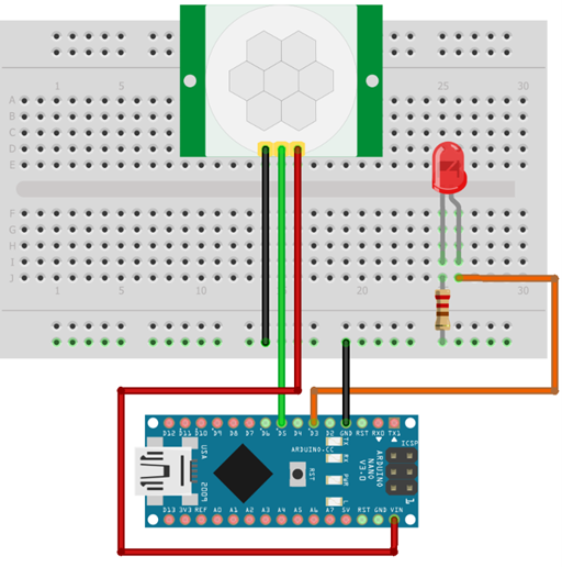
Schematic
Given image show wiring diagram of PIR sensor with Arduino Nano board:
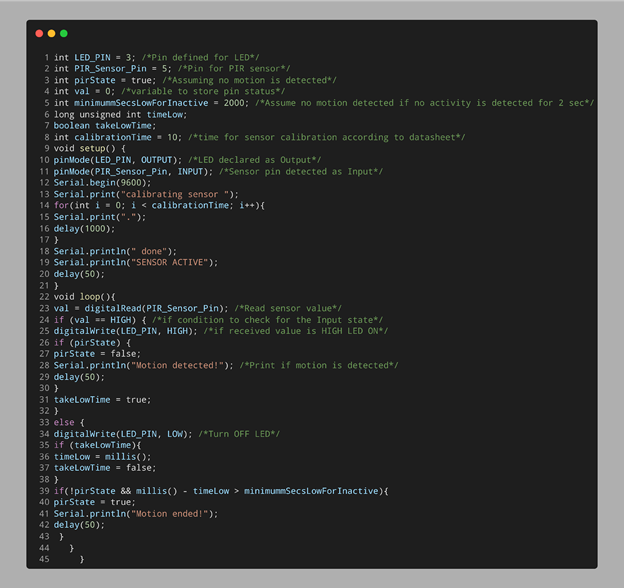
Code
Open IDE (Integrated Development Environment). Select Nano board and click the upload button after writing the below code.
int PIR_Sensor_Pin = 5; /*Pin for PIR sensor*/
int pirState = true; /*Assuming no motion is detected*/
int val = 0; /*variable to store pin status*/
int minimummSecsLowForInactive = 2000; /*Assume no motion detected if no activity is detected for 2 sec*/
long unsigned int timeLow;
boolean takeLowTime;
int calibrationTime = 10; /*time for sensor calibration according to datasheet*/
void setup() {
pinMode(LED_PIN, OUTPUT); /*LED declared as Output*/
pinMode(PIR_Sensor_Pin, INPUT); /*Sensor pin detected as Input*/
Serial.begin(9600);
Serial.print("calibrating sensor ");
for(int i = 0; i < calibrationTime; i++){
Serial.print(".");
delay(1000);
}
Serial.println(" done");
Serial.println("SENSOR ACTIVE");
delay(50);
}
void loop(){
val = digitalRead(PIR_Sensor_Pin); /*Read sensor value*/
if (val == HIGH) { /*if condition to check for the Input state*/
digitalWrite(LED_PIN, HIGH); /*if received value is HIGH LED ON*/
if (pirState) {
pirState = false;
Serial.println("Motion detected!"); /*Print if motion is detected*/
delay(50);
}
takeLowTime = true;
}
else {
digitalWrite(LED_PIN, LOW); /*Turn OFF LED*/
if (takeLowTime){
timeLow = millis();
takeLowTime = false;
}
if(!pirState && millis() – timeLow > minimummSecsLowForInactive){
pirState = true;
Serial.println("Motion ended!");
delay(50);
}
}
}
Code started by defining the input pin for PIR sensor and output pin for LED. An int variable val is defined. This variable will store the state of the PIR output pin.
Next, using the pinMode function, the LED and sensor pin are defined as output and input respectively. A if condition is used. If the Arduino Nano receives HIGH input from the sensor LED will turn ON. Similarly, if no motion is detected a LOW signal will be sent to Arduino resulting in turning the LED OFF.
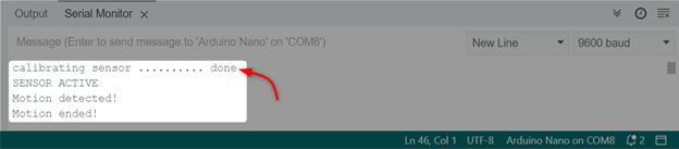
Output
Below output will be displayed once motion is detected by the PIR sensor. First sensor will calibrate itself after that it can detect any motion.
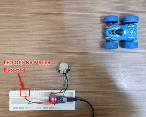
Hardware
The LED is OFF because no motion is detected.
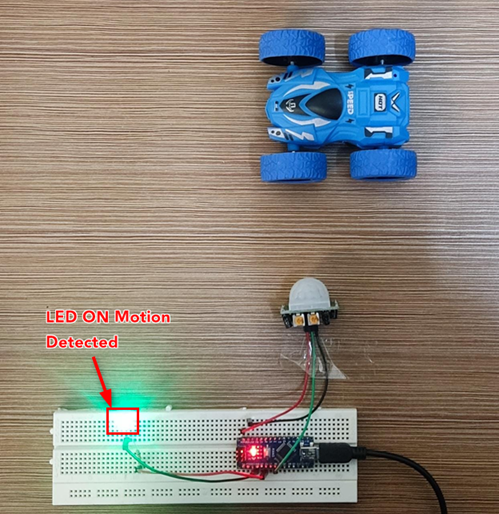
Now the car is moving and the LED is turned ON as motion is detected.
Conclusion
Arduino Nano can be interfaced with different sensors such as PIR. Using this sensor any object motion can be detected. The PIR sensor with Arduino has multiple applications such as home security systems or street lighting. This article covers the complete Arduino code and steps involved in detecting object movement.
Source: linuxhint.com