Interfacing RC522 RFID Sensor with Arduino Nano
Content covered in this article:
- 1: Introduction to RC522 Sensor
- 2: RC522 Sensor Pinout
- 3: Interfacing RC522 RFID Sensor with Arduino Nano
- 4: Reading an RFID Tag Using Arduino Nano
1: Introduction to RC522 Sensor
The MFRC522 is a RFID based contactless IC that can read and write data at a frequency of 13.56 MHz. It is designed for easy integration into a wide range of applications, including access control systems, payment terminals, and other systems that require secure wireless communication.
The sensor features a low power consumption design and is compliant with the ISO/IEC 14443 A/MIFARE standard, which allows it to communicate with a wide range of contactless cards and tags.
Additionally, the MFRC522 features a built-in antenna, making it a convenient and compact solution for adding contactless communication capabilities to a project.
2: RC522 Sensor Pinout
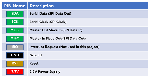
The sensor has a total of 8 pins that interface it with a microcontroller or other control device. The pinout of the MFRC522 sensor is as follows:
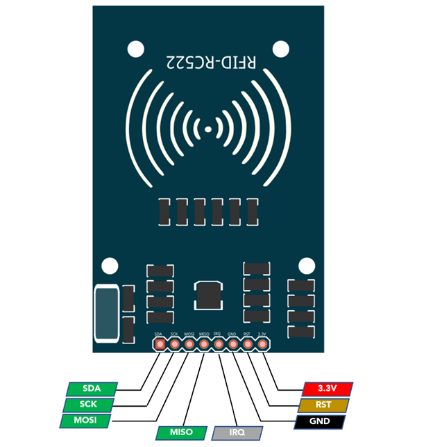
The SDA, SCK, MOSI, and MISO pins are used to interface the MFRC522 sensor with a microcontroller via a 4-wire Serial Peripheral Interface (SPI) communication protocol.
The IRQ pin can be used to generate an interrupt when certain events occur, such as a successful card or tag read, however it is not commonly used in many projects.
The GND pin connects to the ground of the circuit, and the RST pin is used to reset the sensor.
Finally, the 3.3V pin is used to supply power to the sensor.
It is important to note that these pin names may vary slightly depending on the specific module, so it’s always best to consult the manufacturer’s datasheet for the correct pinout information.
3: Interfacing RC522 RFID Sensor with Arduino Nano
Interfacing the MFRC522 sensor with an Arduino microcontroller is a simple process that can be accomplished using the MFRC522 library, which is freely available for download. This library provides an easy-to-use set of functions for accessing the sensor’s functionality, including functions for reading and writing data to contactless cards and tags.
Once the library is installed, an example sketch can be found in the examples menu which demonstrates how to initialize the sensor and communicate with a card or tag. In the sketch, it’s important to set the correct pin connections between the Arduino and the MFRC522 sensor, such as the SPI pins, reset pin and others, according to the model of the Arduino board being used.
With the correct wiring and the library properly installed, the Arduino will be able to communicate with the MFRC522 sensor and perform the desired actions such as reading and writing to cards and tags.
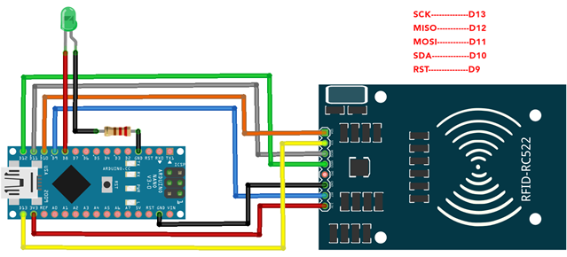
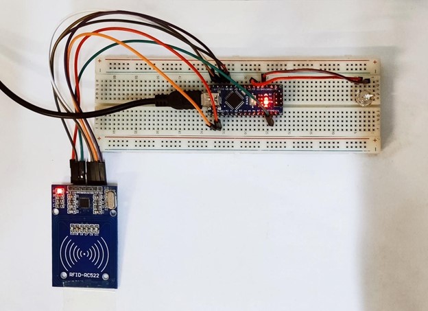
3.1: Schematic
RC522 schematic image with Arduino Nano is shown below:
3.2: Installing the Required Libraries
MFRC522 library is needed for reading the RFID card and tags UID. Open IDE, go to Library Manager and search for the MFRC522 library. Install the library in Arduino IDE:
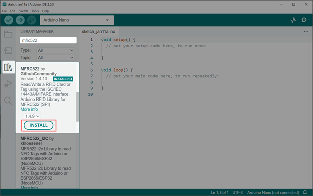
After installing the MFRC522 library we will read the UID for RFID tags and cards.
3.3: Getting the UID for RFID Card/Tag
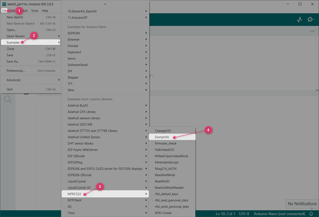
Open the DumpInfo example for MFRC522 sensor. Go to: File>Examples>MFRC522>Dumpinfo
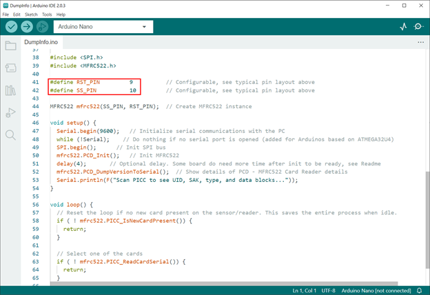
Following code will open in a new IDE window. Upload the code to Arduino Nano. Remember to set the Reset and Slave select pin according to your Arduino board. Any of the Arduino digital pins can be set as RST and SS.
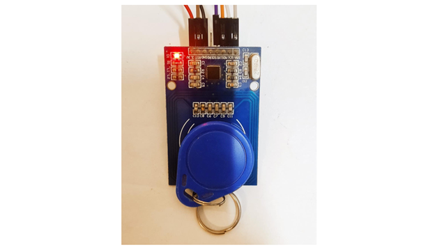
After uploading code to Arduino Nano. Touch and hold the RFID card/tag with MFRC522 sensor.
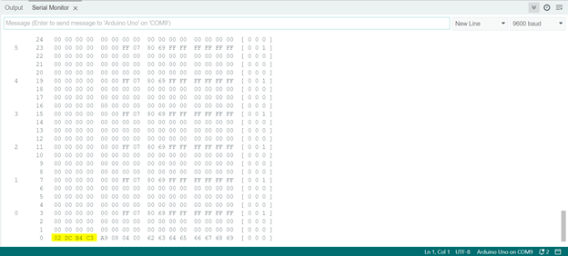
Sensor will read the data saved inside the RFID tag and display it on the serial monitor. Here we can see the UID for RFID tag stating 02 DC B4 C3.
Total of 16 (0-15) sectors in which RFID card/tag 1K memory is organized. Four (0-3) blocks are included in each of these 16 sectors. Each block has capacity to store 16 (0-15) bytes of data.
This data represents that:
16 sectors x 4 blocks x 16 bytes of data = 1024 bytes = 1K memory
The Arduino IDE serial monitor shows us distribution of 1K memory of RFID tag. This distribution also contains the sectors, blocks, and data information in rows and columns of the output data:
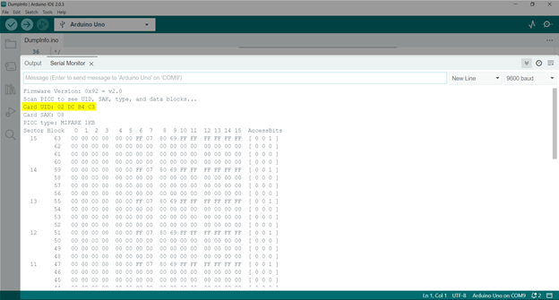
You can also read the Unique ID (UID) for the card at the end of output:
4: Reading an RFID Tag Using Arduino Nano
Now we have read the Unique ID (UID) for RFID tag. We will write an Arduino code that saves this card information and grants access to the user if the RFID tag with the same UID is tapped with the MFRC522 sensor.
4.1: Code
Open IDE, select Nano board and upload the given code:
****************
Linuxhint.com
****************
Linuxhint.com
****************
*/
#include <SPI.h>
#include <MFRC522.h>
#define SS_PIN 10 /*Slave Select Pin*/
#define RST_PIN 9 /*Reset Pin for RC522*/
#define LED_G 8 /*Pin 8 for LED*/
MFRC522 mfrc522(SS_PIN, RST_PIN); /*Create MFRC522 initialized*/
void setup()
{
Serial.begin(9600); /*Serial Communication begin*/
SPI.begin(); /*SPI communication initialized*/
mfrc522.PCD_Init(); /*RFID sensor initialized*/
pinMode(LED_G, OUTPUT); /*LED Pin set as output*/
Serial.println("Put your card to the reader...");
Serial.println();
}
void loop()
{
/*Look for the RFID Card*/
if ( ! mfrc522.PICC_IsNewCardPresent())
{
return;
}
/*Select Card*/
if ( ! mfrc522.PICC_ReadCardSerial())
{
return;
}
/*Show UID for Card/Tag on serial monitor*/
Serial.print("UID tag :");
String content= "";
byte letter;
for (byte i = 0; i < mfrc522.uid.size; i++)
{
Serial.print(mfrc522.uid.uidByte[i] < 0x10 ? " 0" : " ");
Serial.print(mfrc522.uid.uidByte[i], HEX);
content.concat(String(mfrc522.uid.uidByte[i] < 0x10 ? " 0" : " "));
content.concat(String(mfrc522.uid.uidByte[i], HEX));
}
Serial.println();
Serial.print("Message : ");
content.toUpperCase();
if (content.substring(1) == "02 DC B4 C3") /*UID for the Card/Tag we want to give access Replace with your card UID*/
{
Serial.println("Authorized access"); /*Print message if UID match with the database*/
Serial.println();
delay(500);
digitalWrite(LED_G, HIGH); /*Led Turn ON*/
delay(2500);
digitalWrite(LED_G, LOW);
}
else {
Serial.println(" Access denied"); /*If UID do not match print message*/
}
}
Code started by including the SPI and MFRC522 library. Next, we defined the Reset and Slave select pin for the sensor. A LED at pin D8 is initialized as output.
The RFID card which we want to read is initialized by defining the UID. This is the same UID we got using the DumpInfo example code:

An IF condition will check the UID for the card which is tapped with the sensor. If the UID matches the one inside the code LED will turn on and Authorized Access message will be printed, else LED will remain OFF and Access denied message will appear if any other card is tapped.

4.2: Output
In output we can see the RFID tag is not tapped with MFRC522 sensor, so no LED is ON:
Touch or bring the RFID card/tag near the sensor following output will appear on the serial monitor displaying the card UID:
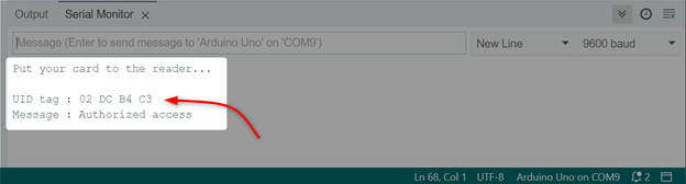
LED is turned ON if the access is granted and UID matches with the one we defined inside the code:
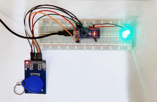
We have completed interfacing of RFID tag with RC522 sensor using Arduino Nano board and IDE.
Conclusion
Arduino nano is a power conserving board that has several GPIO pins to take input from different sensors. Arduino Nano comes with built-in support for UART, SPI and I2C protocol which allows use of sensors using these Arduino communication protocols. This article covers Arduino Nano interfacing with RC522 sensor and code required to read any RFID card/tag.
Source: linuxhint.com