How to Use Raspberry Pi GPIO Pins – Python Tutorial
GPIO Pins on Raspberry Pi-Python Tutorial
GPIO or General-Purpose Input/Output Pins are the key component of the Raspberry Pi board since through these pins you can control any circuit right from your system. In Raspberry Pi 4, they are 40 GPIO pins, which are highlighted in the image below:

The pin labels are shown in the image below, and only those pins that start with the name GPIO are programmable:
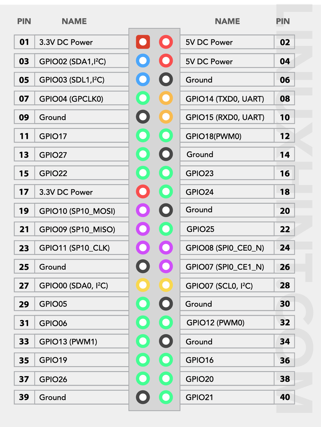
For details about these pins’ headers, follow this.
How to Use Raspberry Pi GPIO Pins – Python Tutorial
Raspberry PI OS comes with a pre-installed Python editor called Thonny Python IDE that allows users to code the GPIO pins in Python. The steps to write a python code using the Thonny Python editor are mentioned below with an example:
Step 1: Open Python Editor
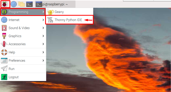
To use the Python editor, go to the Application Menu, select the “Programming” option to open the Thonny Python IDE on Raspberry Pi desktop.
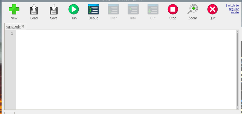
The Thonny Python interface will appear on the screen as shown below:
Step 2: Importing GPIO Module
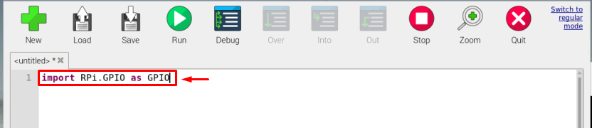
To start using the GPIO pins, you have to import the GPIO library using the following code.
The GPIO library is used before writing the code since it allows you to control the GPIO pins. This library is already installed by default on the Raspberry Pi system.
By using this command, we are just importing this RPi.GPIO module and calling it as GPIO so that we can just simply use the GPIO instead of writing the whole name again and again in the code.
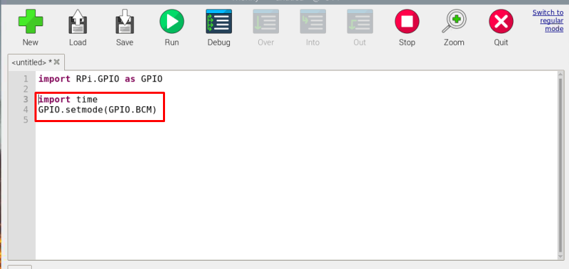
Step 3: Import Time and Configure GPIO
Now, for our example, you have to import the time module and set the GPIO pins using the following code as this will help you later in the code to use time constraints and utilize the GPIO pin later in the code.
GPIO.setmode(GPIO.BCM)
Note: The BCM with GPIO in the command represents the Broadcom Channel numbers of pins:
The Broadcom channel number is fixed for instance some GPIO numbers are shared below:
| Physical Board Pin Number | GPIO Number |
|---|---|
| Pin 11 | 17 |
| Pin 12 | 18 |
| Pin 13 | 27 |
| Pin 15 | 22 |
See the above GPIO table for further guidance.
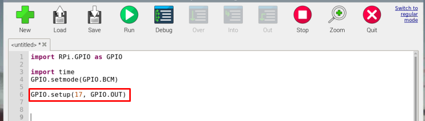
Step 4: Pin Configuration
Now, finally it’s time to think about what you are interested in using the GPIO pins. If you have to display the output using GPIO pins then you have to configure the GPIO as an output pin and if you are using some sensor or a device that needs to be attached as an input device, configure the pin as the input pin such as GPIO.setup (22, GPIO.IN).
In the example below, I am using GPIO 17 (which is pin number 11 on the board) as an output because I will use this pin to light up the LED.
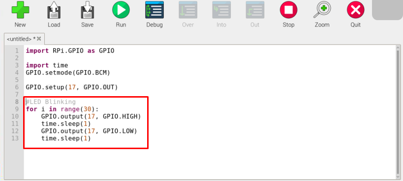
Step 5: Write Code
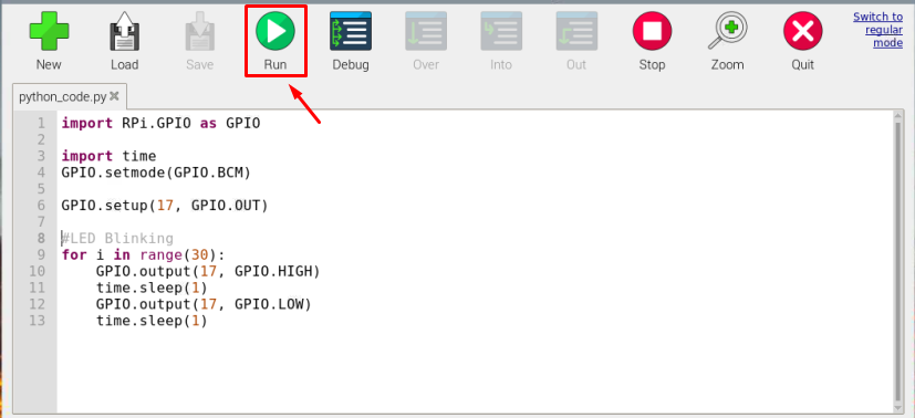
The below code can be utilized to toggle the LED on Raspberry Pi. You can use the same code or use a different one because the code is provided for your guidance.
Since I am toggling or blinking the LED for 30 times, so “for” loop is used. Further, the GPIO.HIGH is used to turn on the LED. The time.sleep is used to hold the state for 1 second before turning off the LED using the GPIO.Low code:
Note: You can change the Pin number and time for LED blinking according to your choice.
GPIO.output(17, GPIO.HIGH)
time.sleep(1)
GPIO.output(17, GPIO.LOW)
time.sleep(1)
Step 6: Save the File
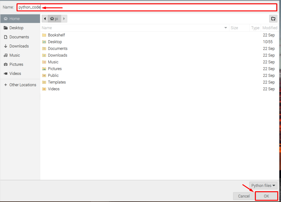
After completing the code, save the file using the “Save” button from the menu bar.
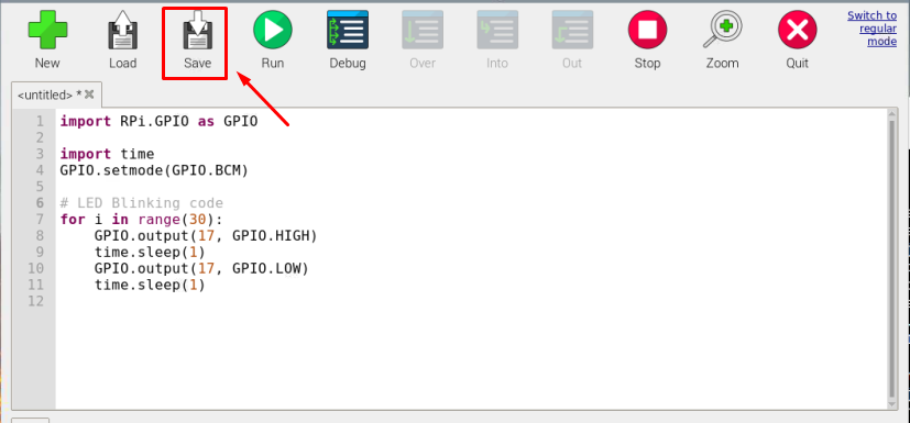
Choose an appropriate name for your file. In my case, it’s “python_code”.
Step 7: Build the Circuit
Now the coding part is completed, it’s now time to test the code. However, before that, you must create a circuit using the code you just created in the above steps.
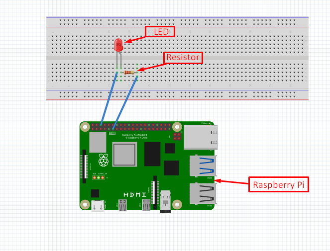
To create the circuit for LED blinking, follow the guidelines given below:
- The positive terminal of a LED is connected to GPIO 17 (pin 11 on board) and the negative terminal of the LED is connected to the Ground (pin 6 on board).
- A resistor is connected to the positive terminal of the LED so that the LED won’t burn due to excessive voltage. If you are using LED with an in-built resistor then you can skip the resistor.
Follow the below-given circuit for a better picture.
Step 8: Run the Code
Once the circuit is completed, you can run the code using the “Run” button on the Thonny IDE to see if the LED starts blinking.
Output:
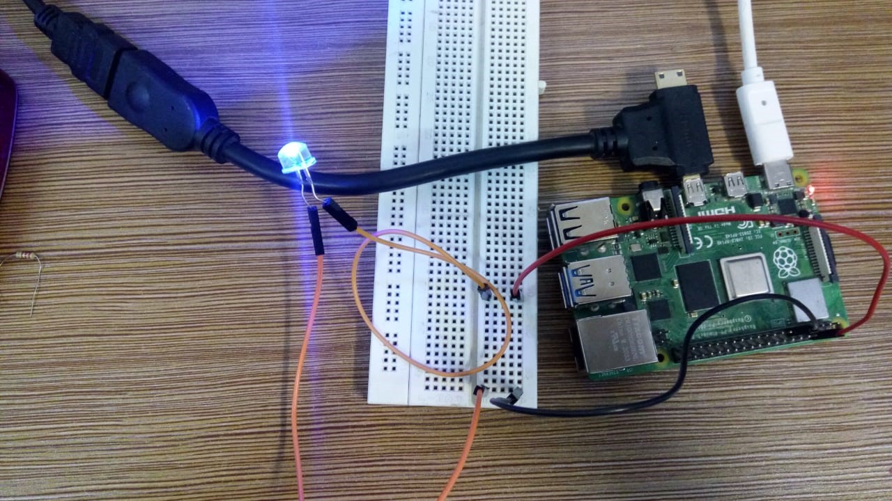
The output of my code can be seen in the below image, the LED has blinked 30 times with a one-second delay between each Off and On state.
Note: In the below circuit I have used an LED with a built-in resistor so no separate resistor is attached.
That’s all for this guide, in a similar way other complex circuits can also be built and can be controlled by Python with Raspberry Pi.
Conclusion
The Raspberry Pi has a default Python editor known as Thonny Python IDE which can be used to write various python codes. To control the Raspberry Pi GPIO pins, the users just have to import the “RPI.GPIO” library in the Python code and simply configure the pins as an output or input pin using the GPIO number. After that, they can write the python code to perform any action like LED blinking already shown in the above guidelines.
Source: linuxhint.com