How to Use MOSFET as a Switch
MOSFET as a Switch
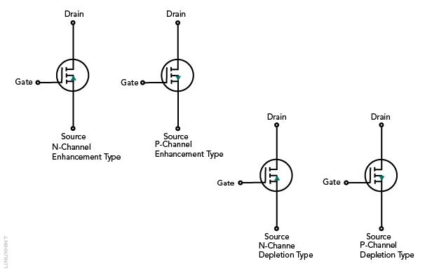
There are different types of MOSFET based on their working and construction, such as depletion type MOSFET, enhancement type MOSFET, and also N-type and P-type MOSFET. The formation of a channel is the primary distinction between the D and E types. The MOSFET channel is already formed in the D-MOSFET, so it acts as a normal ON switch, but in the case of E-MOSFET channel is formed by applying a voltage between the gate and the source terminal.
Structure of MOSFET
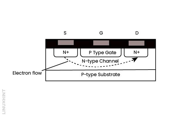
The structure of MOSFET is based on the applications. It acts as a switch when interfaced with any logic gate and is used in communication devices. To obtain high voltage and high current, a number of MOSFETs are connected together, but this is impractical because it is expensive, therefore power FETs come into use. Below given figure shows the N-channel MOSFET in which the source and drain are made by the N-type within the P-type substrates.
Characteristic Curve of MOSFETs
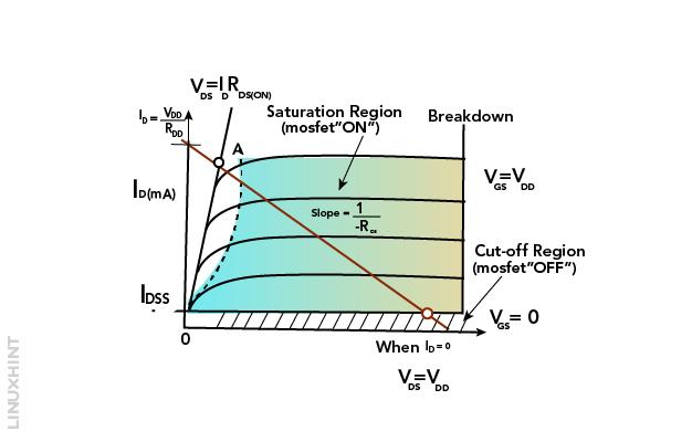
The above-given figure is the characteristic curve of MOSFET. The VI-curve has been used to visualize the minimum ON voltage required for MOSFET for the proper working. As shown in the figure, when the input voltage is high or VGS = VDD then the Q-point moves to point A on the load line. On the other hand, if the input voltage becomes low then Q-point moves to point B. The value of the drain current ID starts increasing when the resistance of the channel becomes low.
Characteristic of MOSFETS
The characteristics of MOSFETs are shown in the characteristic curve, which are directly related to its functions:
Let’s start with first switching mode:
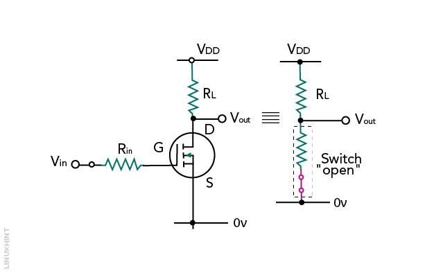
Cut Off Region
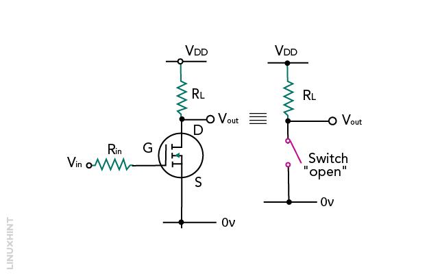
During this region, MOSFET behaves like an open switch, there is no current flow through it. Thus, there would be no channel between the drain and source, following the condition, VGS < VTH. The below figure shows the MOSFET in cut-off mode.
Saturation Region
During this region, the gate is pinch-off among the Source and Drain. It is given the form like VDS < VGS- VTH. In this condition, it acts like a close switch, during which IDC saturated values are passed through it. The below figure shows the MOSFET in saturation mode.
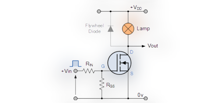
MOSFET as a Switch
The figure shown below is an example of MOSFET as a switch to ON and OFF the lamp. To ON and OFF the lamp the gate must be given with a proper positive signal. A lamp is a resistive load if the load is replaced by an inductive one then an extra flywheel diode is used to protect the MOSFET.
Example of MOSFET
The values of lamps are 3V and 20W, used on the 0.1 Ohm channel of MOSFET, to find out the power dissipation during switching. Firstly, find the current through the lamp:

Now find the dissipation power:


4.43-watt power dissipated during the lamp-on state.
Conclusion
The main function of a MOSFET in any circuit is to perform the functions of a switch. There are different types of MOSFET based on their function and characteristics, such as Depletion type MOSFET and Enhancement MOSFET.
Source: linuxhint.com