How to Scan I2C Address in ESP32 Using Arduino IDE
Introduction to I2C Communication
I2C alternatively known as I2C or IIC is a synchronous master-slave communication protocol where a signal master device can control multiple number of slave devices over a single wire (SDA line).
I2C combine the working of UART and SPI protocols for example SPI supports multiple slave devices control over a single master, I2C also support this on the other hand UART uses two-line TX and Rx for communication I2C also use two-line SDA and SCL for communication.
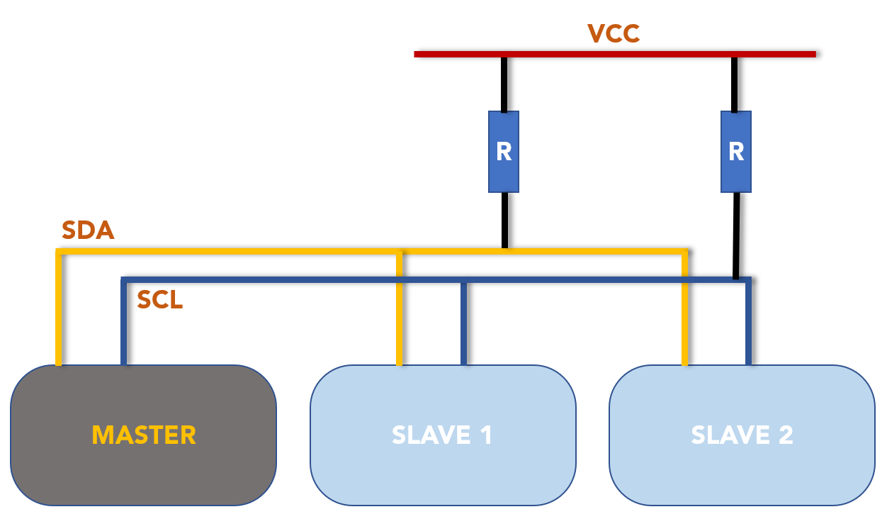
Here we can see we have used pull up resistors with both SDA, SCL lines. This is because by default I2C only outputs two levels of either LOW or open circuit. By default, I2C on all chips is in open circuit mode so to pull them HIGH we used a pull-up resistor.
Following is the two lines I2C uses:
- SDA (Serial Data): Line to transmit and receive data from master to slave and vice versa
- SCL (Serial Clock): Clock signal line to select a specific slave device
ESP32 I2C Bus Interfaces
ESP32 features two I2C bus interfaces using which I2C communication is performed as either master or slave depending on the device which is interfaced with ESP32. According to ESP32 datasheet the ESP32 board I2C interface supports following configuration:
- Standard mode I2C communication at rate of 100 Kbit/s
- Fast or advanced mode I2C communication at speed of 400 Kbit/s
- Dual addressing mode 7-bit and 10-bit
- Users can control I2C interface by programming the command registers
- ESP32 I2C bus interface is more flexible in controlling
Connecting I2C Devices with ESP32
Interfacing devices with ESP32 using I2C protocol is very simple just like UART we only need two lines to connect SDA and the SCL clock line.
ESP32 can be configured as both in Master and Slave mode.
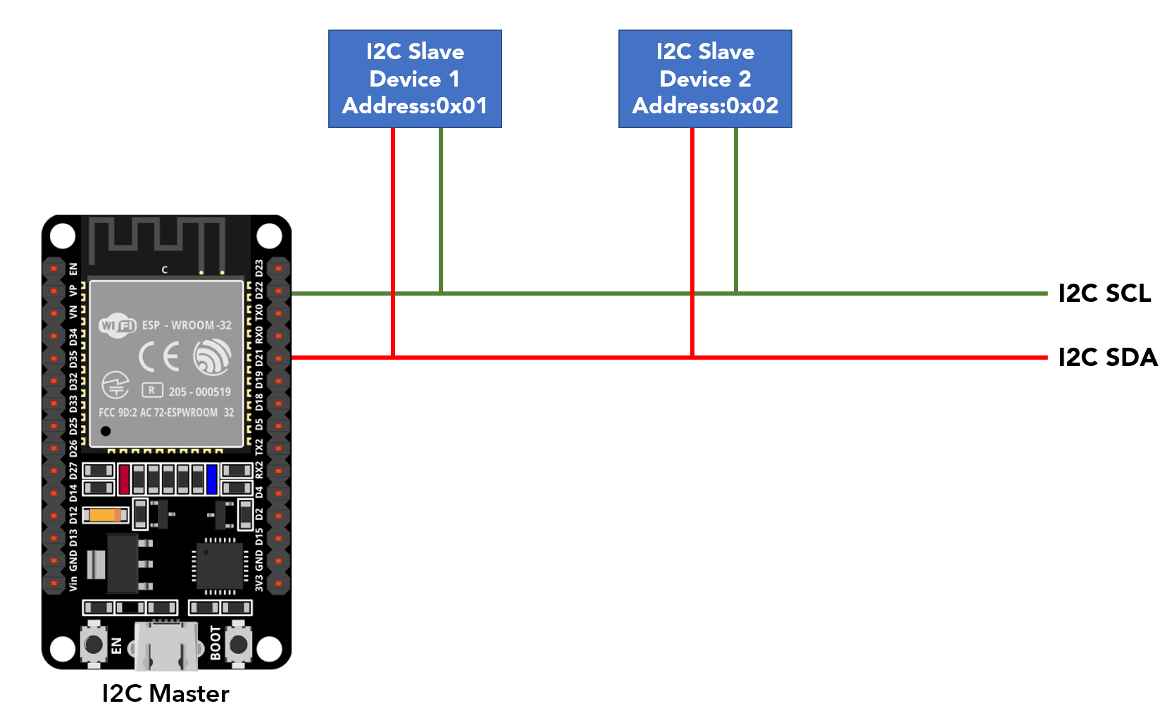
ESP32 I2C Master Mode
In this mode ESP32 generates a clock signal is used which initiates the communication with connected slave devices.
The two GPIO pins in ESP32 which are pre-defined for I2C communication:
- SDA: GPIO PIN 21
- SCL: GPIO PIN 22
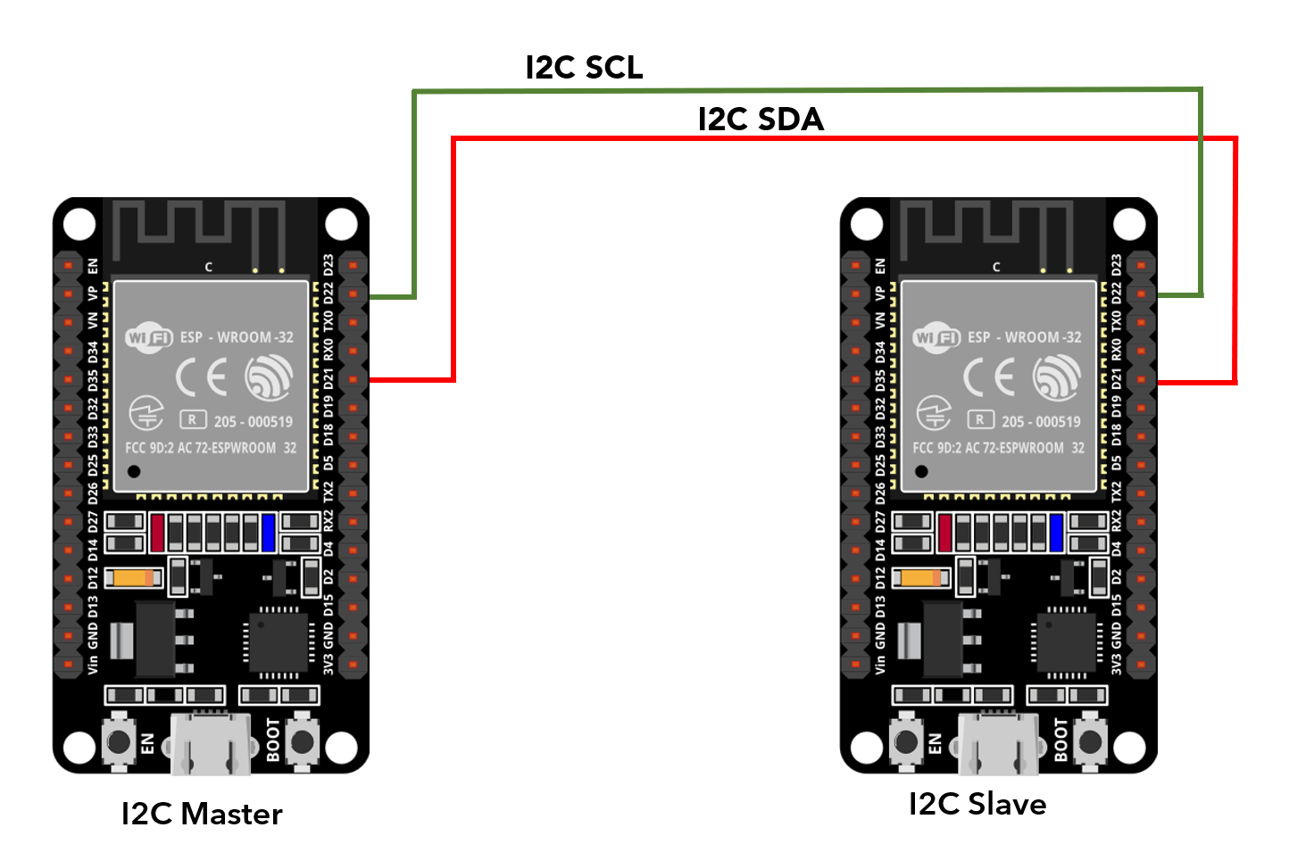
ESP32 I2C Slave Mode
In slave mode the clock is generated by master device. Master is the only device that drives the SCL line in I2C communication. Slaves are the devices that responds to master but cannot initiate a data transfer. In ESP32 I2C bus only the master can initiate data transfer between devices.
Image shows two ESP32 boards in master-slave configuration.
As of now we have understood the working of I2C mode in ESP32 now we can easily find the I2C address of any device by uploading the given code.
How To Scan I2C Address in ESP32 Using Arduino IDE
Finding the I2C address of connected devices with ESP32 is important because if we are using devices with the same I2C address then we cannot communicate with them over a single bus line.
Each I2C device must contain a unique address and the address range from 0 to 127 or (0 to 0X7F) in HEX. For example, if we are using two OLED displays of the same model number or product both will have the same I2C address so we cannot use both on the same I2C line in ESP32.
To find an IC address let’s take an example.
Schematic
Below image shows schematic diagram of OLED display interfacing with ESP32 board using the I2C communication protocol.
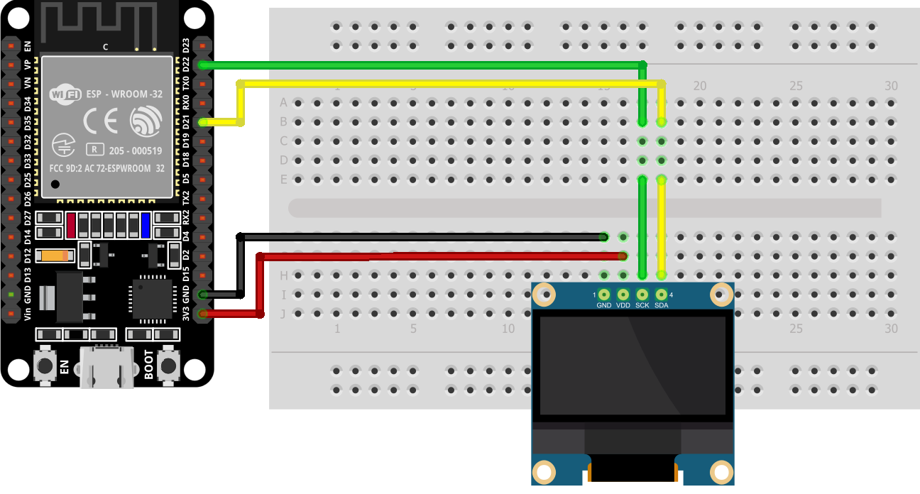
The connection of ESP32 with OLED includes:
| OLED Display | ESP32 Pin |
|---|---|
| VCC | 3V3/VIN |
| GND | GND |
| SCL | GPIO 22 |
| SDA | GPIO 21 |
Code
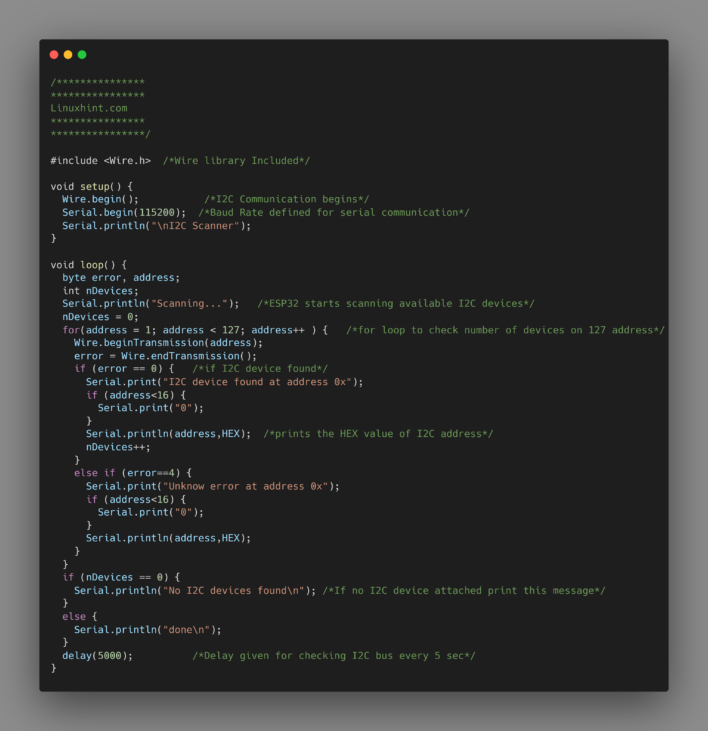
Open Arduino editor and upload the given I2C scanning code in ESP32 board. Make sure ESP32 is connected, and the COM port is selected.
****************
Linuxhint.com
****************
****************/
#include <Wire.h> /*Wire library Included*/
void setup() {
Wire.begin(); /*I2C Communication begins*/
Serial.begin(115200); /*Baud Rate defined for serial communication*/
Serial.println("\nI2C Scanner"); /*print scanner on serial monitor*/
}
void loop() {
byte error, address;
int nDevices;
Serial.println("Scanning…"); /*ESP32 starts scanning available I2C devices*/
nDevices = 0;
for(address = 1; address < 127; address++ ) { /*for loop to check number of devices on 127 address*/
Wire.beginTransmission(address);
error = Wire.endTransmission();
if (error == 0) { /*if I2C device found*/
Serial.print("I2C device found at address 0x");/*print this line if I2C device found*/
if (address<16) {
Serial.print("0");
}
Serial.println(address,HEX); /*prints the HEX value of I2C address*/
nDevices++;
}
else if (error==4) {
Serial.print("Unknown error at address 0x");
if (address<16) {
Serial.print("0");
}
Serial.println(address,HEX);
}
}
if (nDevices == 0) {
Serial.println("No I2C devices found\n"); /*If no I2C device attached print this message*/
}
else {
Serial.println("done\n");
}
delay(5000); /*Delay given for checking I2C bus every 5 sec*/
}
The above code will scan for the available I2C devices. Code started by calling the wire library for I2C communication. Next serial communication is started using the baud rate.
In the loop part of I2C scanning code two variable names, error and address are defined. These two variables store the I2C address of devices. Next a for loop is initialized that will scan for the I2C address starting from 0 to 127 devices.
After reading the I2C address the output is printed on the serial monitor in HEX format.
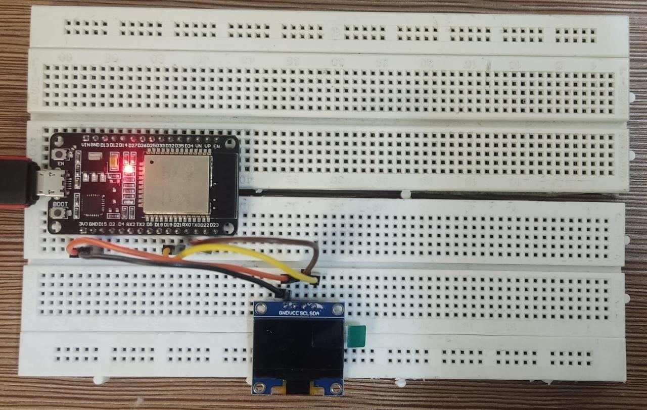
Hardware
Here we can see the OLED 0.96-inch I2C display is connected to the ESP32 board at GPIO pins 21 and 22. Vcc and GND of the display are connected with ESP32 3V3 and GND pin.
Output
In the output we can see the I2C address of the OLED display connected to the ESP32 board. Here the I2C address is 0X3C so we cannot use any other I2C device with the same address for that we have to change the I2C address of that device first.
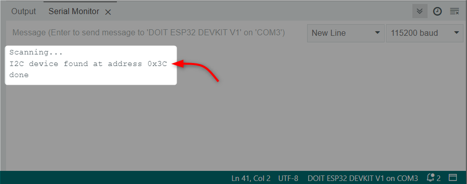
We have successfully obtained the I2C address of the OLED display connected with the ESP32 board.
Conclusion
Finding an I2C address while connecting multiple devices with ESP32 is important as devices which share the same I2C address cannot be connected over a single I2C bus. Using the code above one can identify the I2C address and if the address of any two devices match it can be changed accordingly depending upon the device specifications.
Source: linuxhint.com