How to Design Band Stop Filters and Notch Filters Tutorial
Band Stop Filter
A Band Stop filter also known as band rejection filter is a filter used in electronics and signal processing which blocks the frequencies which lie between its two cut-off frequencies and allows the rest of the frequencies to pass through it.
The parallel combination of a low pass and high pass filter forms the band stop filter. Band stop filter is a two-pole filter, which means it has two cut off frequencies; upper cut of frequency fH and lower cut off frequency fL. So the filter will pass all the frequencies above and below these two frequencies while blocking the frequencies in between of these.
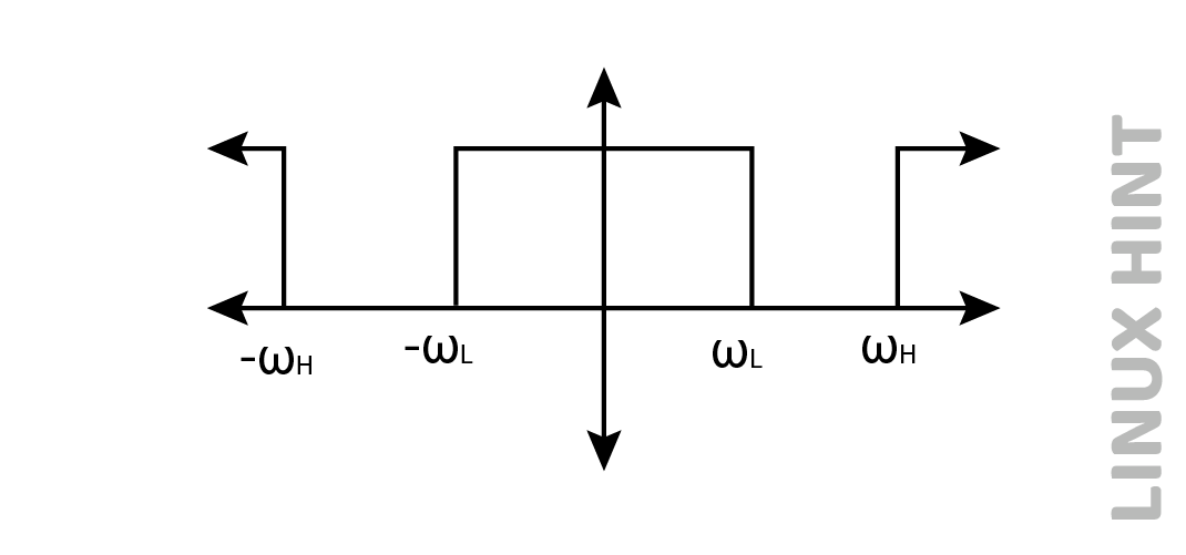
In the figure above the ‘WL’ and ‘WH’ represent the cut off frequencies for the low and high pass filter, respectively.
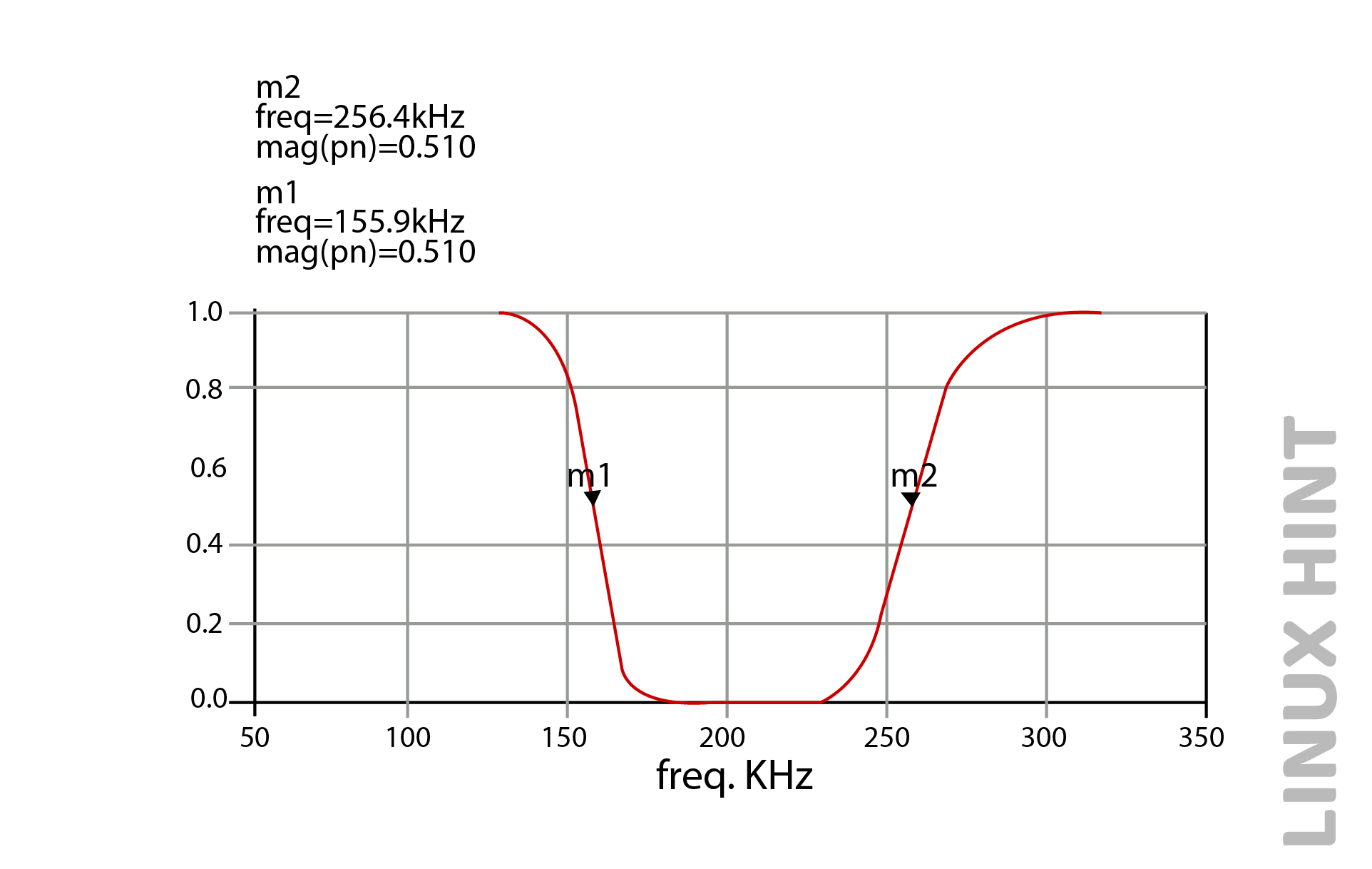
The above graph is for the cut off frequencies as 155.9KHz-256.4KHz. The rest of the frequencies are being passed by the filter.
Working Principle of Band Stop Filter
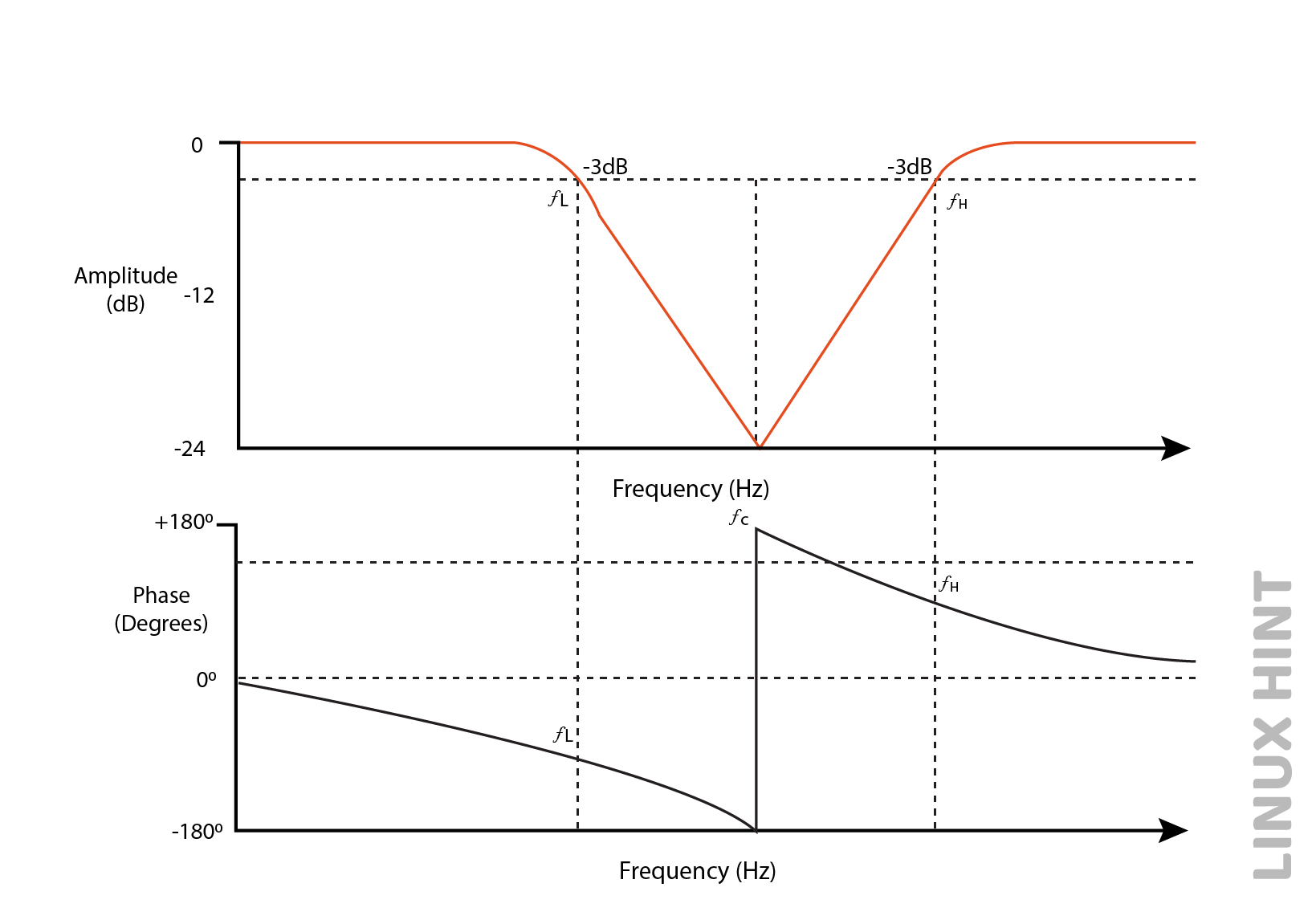
When the signal is fed with the input the high pass filter allows the higher frequencies to pass and a low pass filter allows the lower frequencies to pass thus blocking the other range of frequencies. The ideal response of frequency shown by the band stop filter is demonstrated in the figure below.
RLC Design of Band Stop Filter
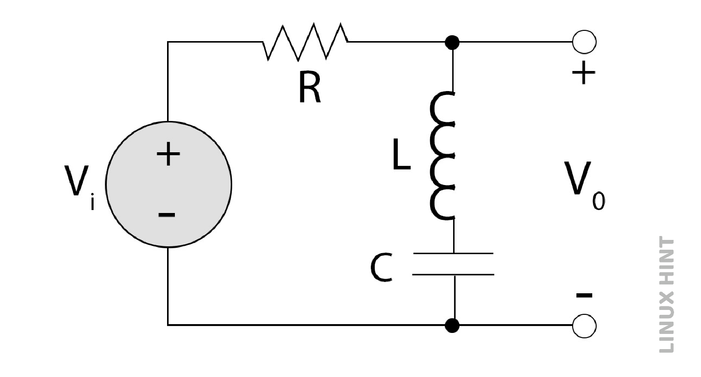
Resistor, inductor, and capacitor are connected to form a circuit as shown in the figure below. The inductor and capacitor are connected in series and the output is taken across them. The circuit will act as open or short based on frequency fed at the input. At higher frequencies the capacitor acts as a short circuit and inductor acts as open circuit and vice versa. Due to the parallel combination of inductor and capacitor at high and low frequencies it acts as an open circuit and passes them through it. While during mid-range it behaves as a short circuit and stops the frequencies from passing through it.
The range of frequencies is set during the design, so they are dependent on the design and the transfer function determines the values of components according to the design.
Notch Filter
If the stop band filter has a narrow range of stop band, then it is referred to as a Notch filter. A notch filter is generally used to remove the single frequency. It is also known as the twin T network due to its two T shaped networks. It has a high Q factor.
Design of Twin-T Notch Filter
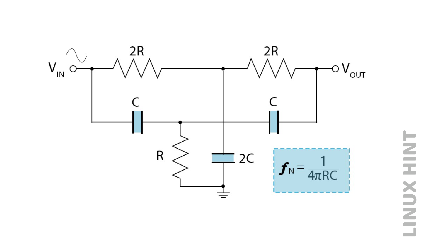
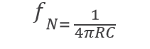
The section of the low pass filter is formed by t-pad configuration of upper resistor 2R and capacitor 2C, however the high-pass filter design is formed by the lower t-pad configuration of resistor R and capacitor 2C. The frequency at which this filter offers maximum depletion is known as Notch frequency and is denoted by fN.
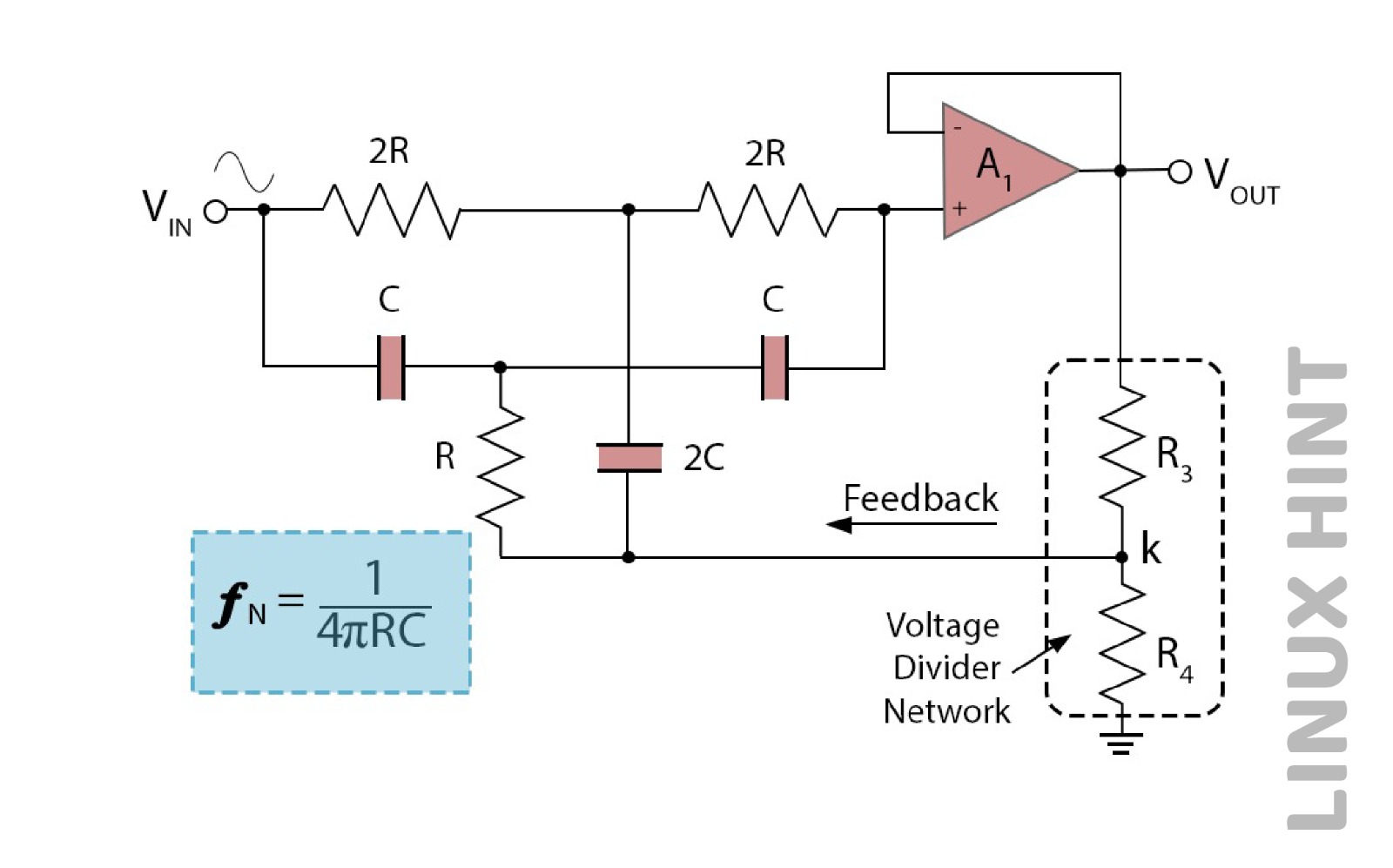
An operational amplifier is used for the designing of a single Op Amp Twin T-notch filter circuit to obtain high level attenuated signals with narrow bandwidth, as represented below.
How To Implement Two Op-Amp RC Notch Filter Design
Design a two Op-Amp narrowband RC notch filter, which has a center notch frequency of 2kHz and 3.5-dB bandwidth of 100 Hz. Consider the 0.4uF capacitor and calculate all the values of the required components to design the filter.
Find the value of R when the given capacitance is 0.4F:

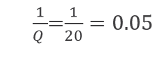
Find the value of Q:

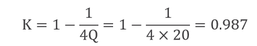
Find the value of K feedback fraction:
Find the value of R3 and R4=

Taking
![]()
then R3 equals:

Find the value of notch depth in dBs:
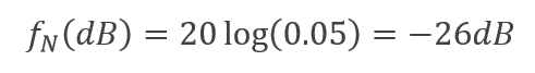
Substituting values in the circuit, the notch filter is designed as:

Conclusion
Band Stop filter is a filter used in electronics and signal processing which blocks the frequencies which lie between its two cut-off frequencies and allows the rest of the frequencies to pass through it. If the stop band filter has a narrow range of stop band, then it is referred to as a Notch filter.
A notch filter is generally used to remove the single frequency. In audio processing systems, band-stop filters are used to suppress specific frequencies that cause humming or hissing noises. It makes the audio clear and noise free. Band-stop filters help in rejecting certain frequencies, by eliminating radio frequency interference in various communications systems.
Source: linuxhint.com