How to Calculate Impedance and Complex Impedance
Impedance is a measure of ability for limiting the current flow. It can take various simple and complex forms in a variety of different configurations of electrical circuits. This article describes in detail the calculation of impedance in different situations.
Impedance
Impedance is defined as the total amount of limitation offered to the flow of electric current. It can range from a simple value of resistance to overall resistance & reactance of complex AC circuits. For DC circuits, the load is all resistive, so impedance is the sum of resistances connected in circuit. For AC circuits, the loads can consist of resistances, inductances, and capacitance, so impedance shall be the sum of all resistance and reactance in the circuit.
Mathematical Expression & SI Units
Impedance is denoted by the letter ‘Z’ and units of impedance are ohms.
Impedance can be expressed in place of resistance in ohm’s law:

Voltage can be calculated in terms of impedance as.

Current can be calculated in terms of impedance as:

Impedance Representation
It is because resistance is not a frequency dependent element. It means, whether frequency goes high or low, the value of resistance would be the same. However, in the case of inductors and capacitors, frequency plays a vital role. The reactance varies with the frequency, as these are frequency dependent elements.
Impedance in AC circuits is just not a simple sum of resistances and reactance in the circuit. In case of resistance, the current and voltages remain in the same phase and there is no phase angle between them. Therefore, in case of inductor and capacitor, there is phase shift between voltage and current and therefore the net impedance value shall be presented with both values of magnitude and phase angle.

Impedance is sometimes also represented using imaginary expression as:

Resistive and Inductive Circuit (RL)
Consider a case of resistance and inductor combination in the electrical circuit as shown below:

In case of resistance and inductance combination, the net sum shall also include the aspect of the phase angles. To determine the sum with respect to phase angles, we can plot the two elements’ vectors in x-y plane as shown below:
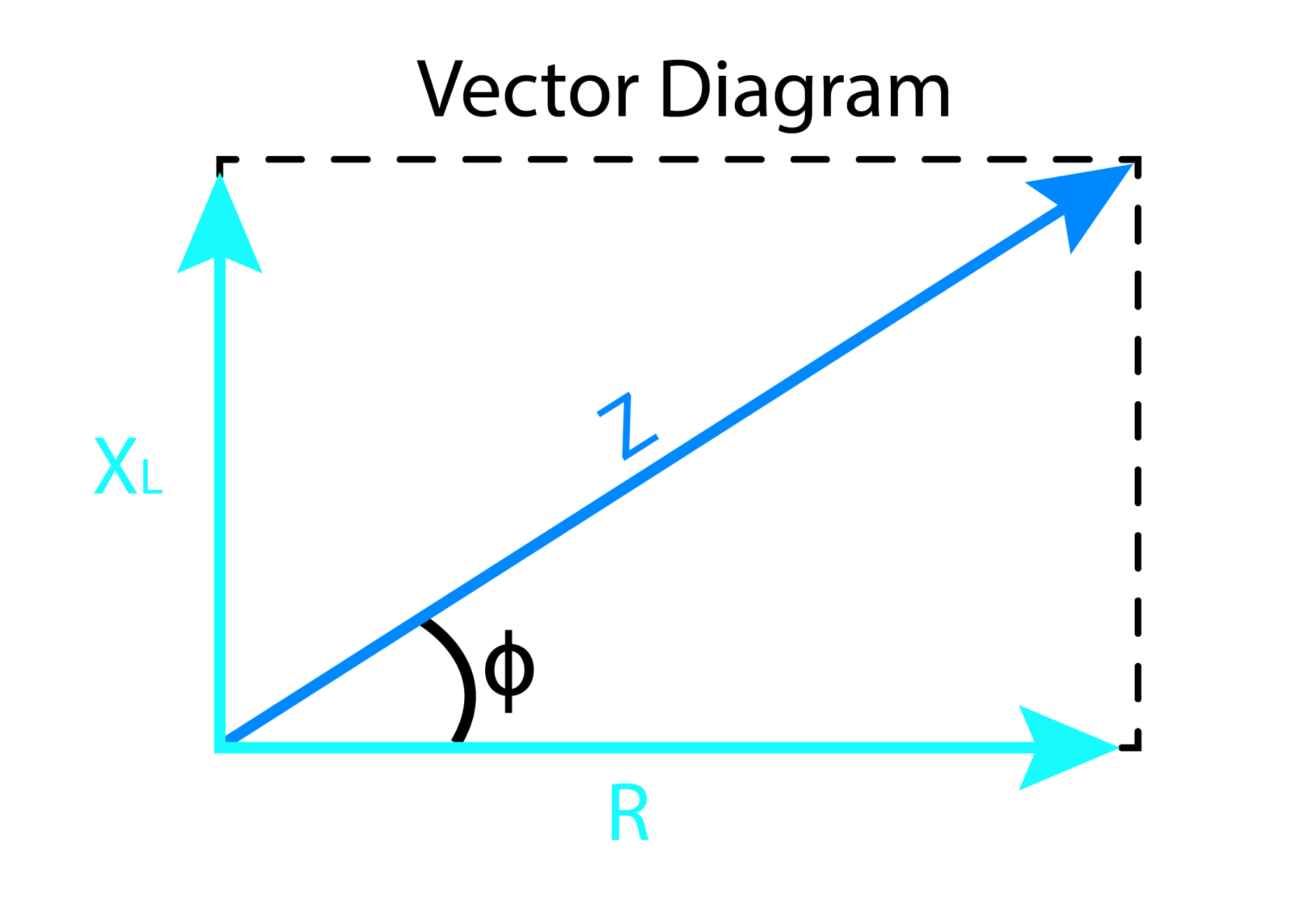
The above vector diagram depicts phase shift of exactly 90 degrees between inductive reactance XL and resistance R. It is because voltage and current are in phase for the resistor, but voltage leads current by almost 90 degrees in inductors, therefore XL is plotted at 90 degrees angle from resistance ‘R’.
The addition of two vectors provides the resultant vector Z at the origin. The vectors can be re-arranged in the form of right-angle triangle below:

Applying Pythagoras theorem for simplification of hypotenuse representing ‘Z’:

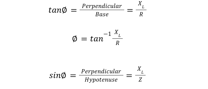
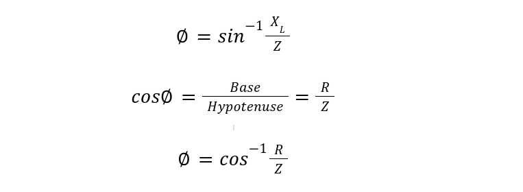
Phase Angle in RL Circuit
The phase angle φ can be calculated in a variety of ways below:
Resistive and Capacitive Circuit (RC)
Consider resistance and capacitor combination in a circuit as shown below:

Capacitors behave oppositely to that of inductors in terms of phase angles. In the case of capacitors, voltage lags current by 90 degrees. So, the vector of the capacitor is shown in the negative y-axis, indicating lag in terms of voltage.

Applying Pythagoras theorem on hypotenuse presenting ‘Z’:


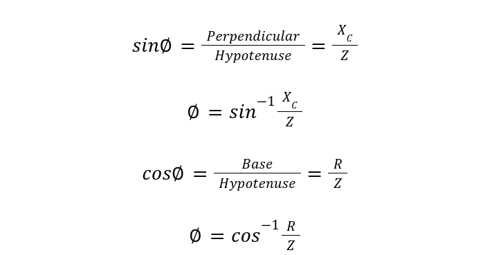
Phase Angle in RC Circuit
Phase angle can be calculated in a variety of ways, listed below:

Resistive, Capacitive and Inductive Circuit (RLC Circuit)
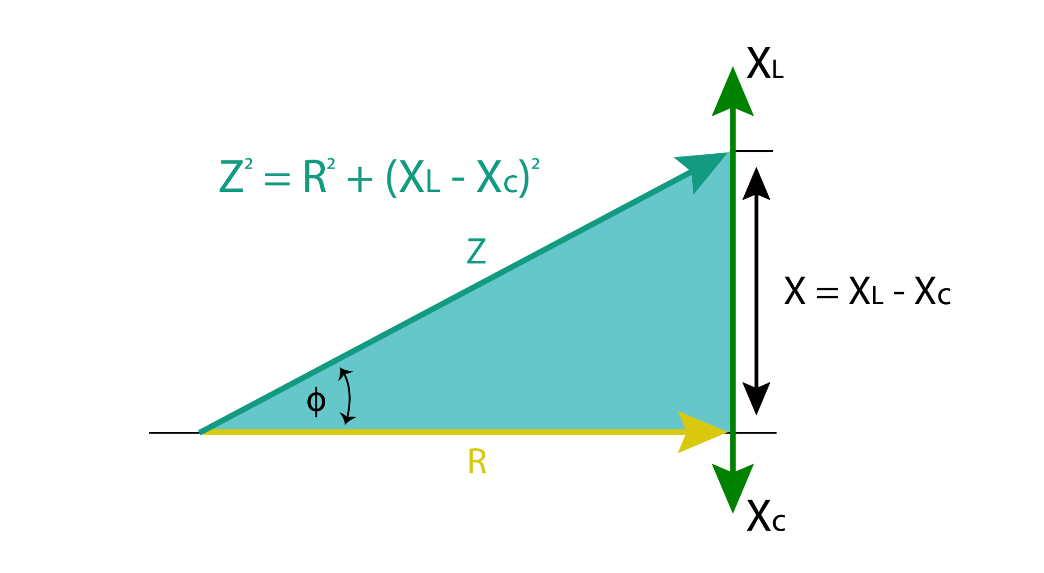
The reactance X shall be the sum of capacitive and inductive reactance. As seen above, inductance is shown with the vector pointing upwards while the capacitor is shown pointing downwards, so we shall consider Xc with negative sign.

So net impedance for RLC circuit is:


The impedance can be plotted in triangle presentation, but the resultant vector can be pointed in both positive and negative planes depending on the result of XL-XC. In the case below, the value of XL is greater, so a triangle is obtained in XL direction. If, in case, the value of XC is greater, the triangle shall be drawn downwards corresponding to the direction of XC.
Resonance in RLC Circuit
The reactance of capacitor and inductor are functions of frequencies. If frequency is chosen in a manner that inductive reactance value matches with capacitive reactance, the subtraction in the final equation will produce zero. In this case, the circuit is said to be in resonance. The only impedance in resonance is the resistance of the circuit.

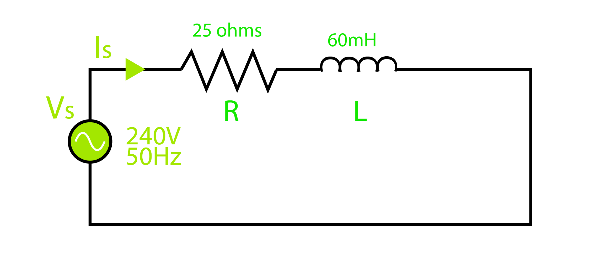
Example 1: Complex Impedance in RL Circuit
A 60mH inductor with 25Ω resistor is connected in a circuit. What will be total impedance and phase angle at 50Hz.
Whereas:


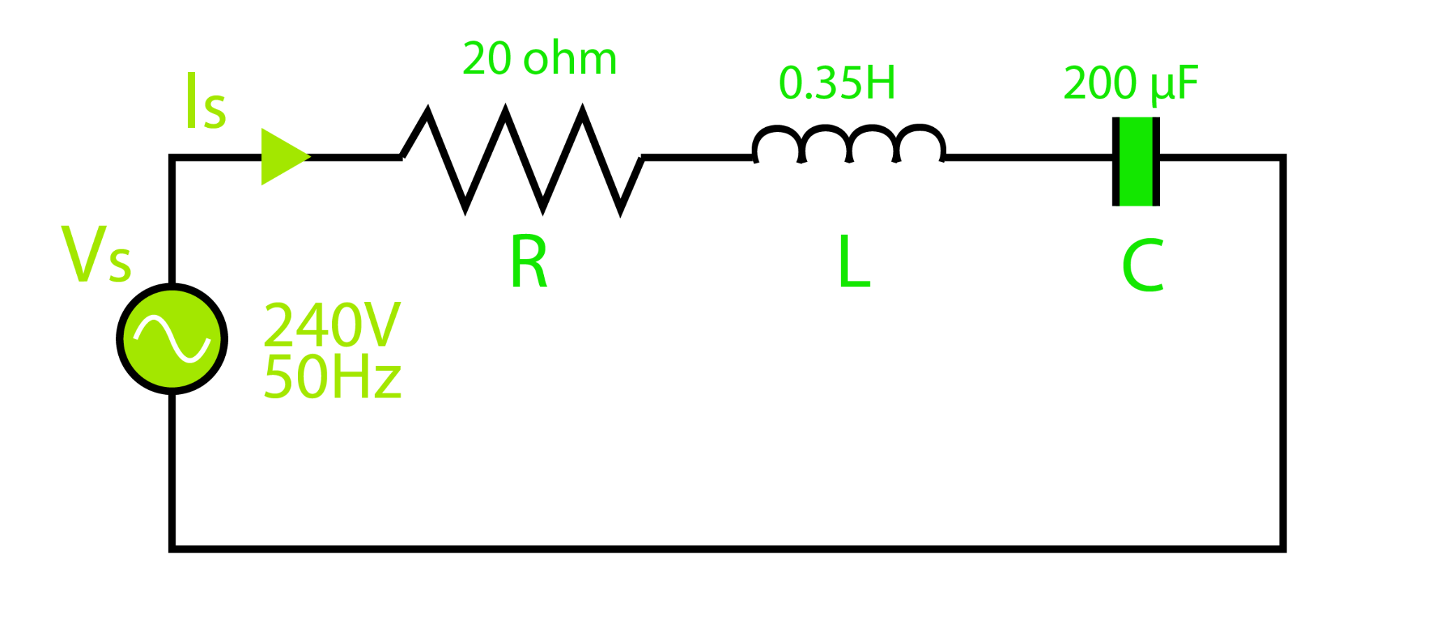
Example 2: Complex Impedance in RLC Circuit
Calculate complex impedance and power factor for below RLC circuit with resistance 20-ohm, inductance 0.35H, capacitance 200uF connected across voltage supply 230V, 50Hz
The Complex Impedance of the RLC circuit is given by:

Calculating inductive reactance:

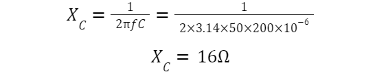
Calculating capacitive reactance:
Complex impedance:

For power factor, using cosφ expression from Pythagoras theorem:

Conclusion
Impedance can take the simplest form of resistance in DC circuits. It can take complex forms in RLC, RC and RL series circuits. In complex forms, it is not merely the sum of resistance and reactance, but it includes effects of phase angles to perform calculations.
Source: linuxhint.com