How Rotary Encoder Works and Interface It with Arduino
Rotary Encoder is an important electromechanical device that has diverse uses in the field of electronics. This article will explain the types and workings of the rotary encoder along with its interfacing with Arduino.
What is a Rotary Encoder
A rotary encoder is a digital input device that senses the angular position of the rotary knob and sends signals to the microcontroller or any other device to which they are connected. They can rotate 360° without stopping. It is also called a shaft encoder. It is used in printers, audio electronics, motors, and controllers.
Types of Rotary Encoders
There are mainly two types of rotary encoders that are decided based on the output signal generated by them. These types are named:
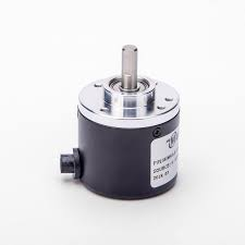
Incremental Rotary Encoder
This type of encoder counts revolutions of the rotary knob in the form of pulses. When the knob is once rotated, a pulse is generated. For every pulse, the counter increments to indicate the angular position of the shaft.
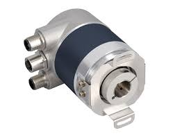
Absolute Rotary Encoder
This type of encoder gives the absolute angular position of the shaft, as it has a separate code for every shaft position, and it measures the angle through that code. It does not need a counter to give an output of angular position. Even if the absolute rotary encoder is de-energized, respective values for angular positions are retained. It is also a low-cost encoder.
Working of Rotary Encoder
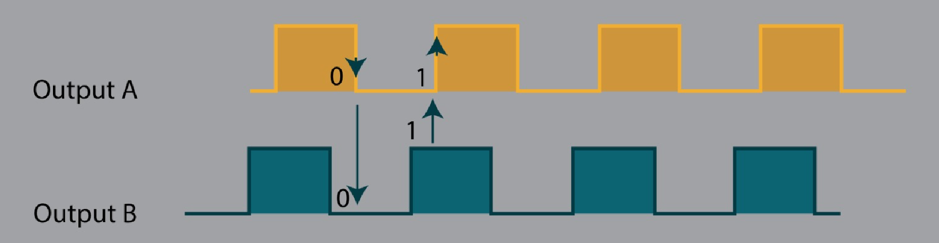
The rotary encoder consists of a disc with equally spaced areas connected to a common pin C that is grounded. The two other pins A and B are contact pins that make contact with C when the rotary knob is rotated. When pin A or B gets connected to the ground, then a signal is generated. These signals generated from output pins are 90° out of phase. This is because pin A gets connected to the ground when the knob is turned clockwise, and pin B gets connected to the ground first when the knob is turned counterclockwise. Therefore, the direction of knob rotation is determined through these connections.
If the state of B is not equal to A, then the knob has turned clockwise.
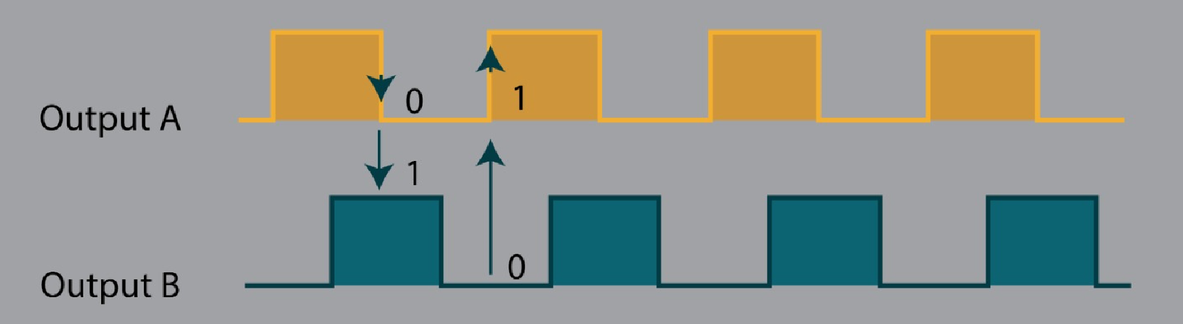
If the state of B is equal to A, the knob has turned counterclockwise.
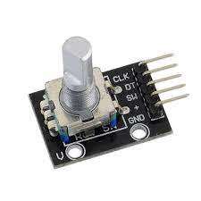
Pin Configuration of Rotary Encoder
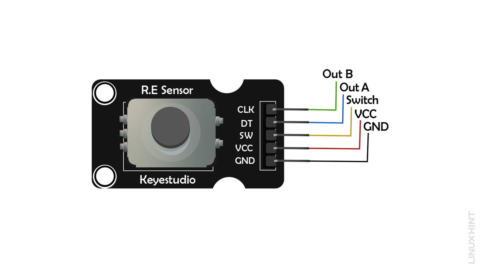
The diagram given below gives a pinout of the rotary encoder that shows output pins A and B, a rotary switch that can be used as a push button, and pins for power supply.
Pin Description of Rotary Encoder
Following is the given description of all rotary encoder pins.
Out B or CLK
This pin gives an output of how many times the knob or rotary encoder has rotated. Each time when the knob is rotated, the CLK completes a cycle of HIGH and LOW. It is counted as one rotation.
Out A or DT
This is the second output pin of the rotary encoder that determines the direction of rotation. It lags 90° behind the CLK signal. Therefore, if its state is not equal to CLK’s state then the direction of rotation is clockwise, otherwise, anti-clockwise.
Switch
The switch pin is used to check if the push button is pressed or not.
VCC
This pin is connected to a 5V supply
GND
This pin is connected to the Ground
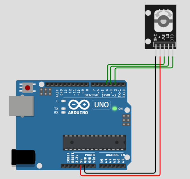
Interfacing Rotary Encoder with Arduino
The rotary encoder has five pins. VCC and GND of the rotary encoder are connected to that of Arduino. The remaining pins CLK, DT, and SW are connected to the digital input pins of Arduino.
Arduino Code for Rotary Encoder
#define CLK_PIN 2
#define DT_PIN 3
#define SW_PIN 4
int counter = 0;
int currentCLKState;
int lastCLKState;
String current direction ="";
unsigned long lastButtonPressTime = 0;
void setup() {
// Set encoder pins as inputs
pinMode(CLK_PIN, INPUT);
pinMode(DT_PIN, INPUT);
pinMode(SW_PIN, INPUT_PULLUP);
// Setup Serial Monitor
Serial.begin(9600);
// Read the initial state of CLK
lastCLKState = digitalRead(CLK_PIN);
}
void loop() {
// Read the current state of CLK
currentCLKState = digitalRead(CLK_PIN);
// If the last and current state of CLK is different, then a pulse occurred
// React to only 1 state change to avoid double count
if (currentCLKState != lastCLKState && currentCLKState == 1) {
// If the DT state is different than the CLK state, then
//The encoder is rotating counter-clockwise, so the decrement
if (digitalRead(DT_PIN) != currentCLKState) {
counter--;
currentDirection = "CCW";
} else {
// Encoder is rotating clockwise, so increment
counter++;
currentDirection = "CW";
}
Serial.print("Rotation Direction: ");
Serial.print(currentDirection);
Serial.print(" | Counter Value: ");
Serial.println(counter);
}
// Remember the last CLK state
lastCLKState = currentCLKState;
// Read the button state
int buttonState = digitalRead(SW_PIN);
// If we detect a LOW signal, the button is pressed
if (buttonState == LOW) {
// If 50ms have passed since the last LOW pulse, it means that the
// button has been pressed, released, and pressed again
if (millis() - lastButtonPressTime > 50) {
Serial.println("Button Pressed!");
}
// Remember the last button press event time
lastButtonPressTime = millis();
}
// Put in a slight delay to help debounce the reading
delay(1);
}
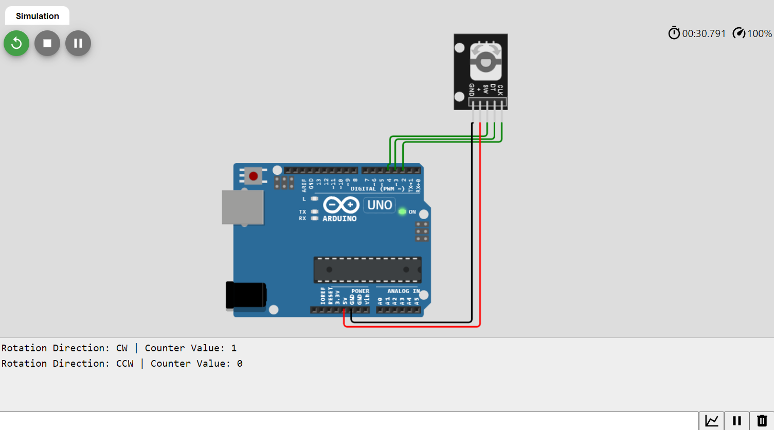
In the above-given code, the state of the CLK pin is checked in the loop() function. If it is not equal to its previous state, it shows that the rotary knob has rotated. Now, to check the direction of knob rotation, the present state of CLK is compared with the state of DT. If both states are unequal, it shows that the knob has rotated clockwise and counter increments its value to show the position of the rotary knob. In the opposite case, counter decrements.
Conclusion
Rotary encoders are advanced position sensors that can rotate continuously. They are available in two types: incremental and absolute. The rotary encoder works by counting pulses generated due to the rotation of the knob. It has diverse applications in daily life electronics to industrial automation.
Source: linuxhint.com