Full Wave Rectifier with Capacitor Filter
Outline:
A Capacitor as a Filter
Full Wave Rectifier
Center Tapped and Bridge Rectifier difference
Conclusion
A Capacitor as a Filter
A capacitor is a reactive device whose reactance varies based on the applied frequency, and this means that the effect of the capacitor on the signal will be based on the frequency. Since the filters also greatly involve the frequencies, that is why a capacitor is used on filters. Moreover, the capacitors are passive components as they do not require energy to operate and are thus used in the passive filter circuits.
Normally, a capacitor becomes an open circuit when it is fully charged and normally the reactance on a higher frequency is low, so the capacitor acts as a short circuit thus allowing the high frequency to pass. On the other hand, when the frequency is low the reactance of the capacitor is high which makes it difficult for the low frequency to pass. The ripples and other transients most of the time have quite a low frequency, so that is why the capacitor blocks them.
Full Wave Rectifier
As mentioned above, the rectifier is a circuit that converts the AC supply to DC with the help of diodes. The circuit for the rectification can be designed in two ways, one is by using two diodes and the other is by making a bridge of four diodes.
Center Tapped Full Wave Rectifier
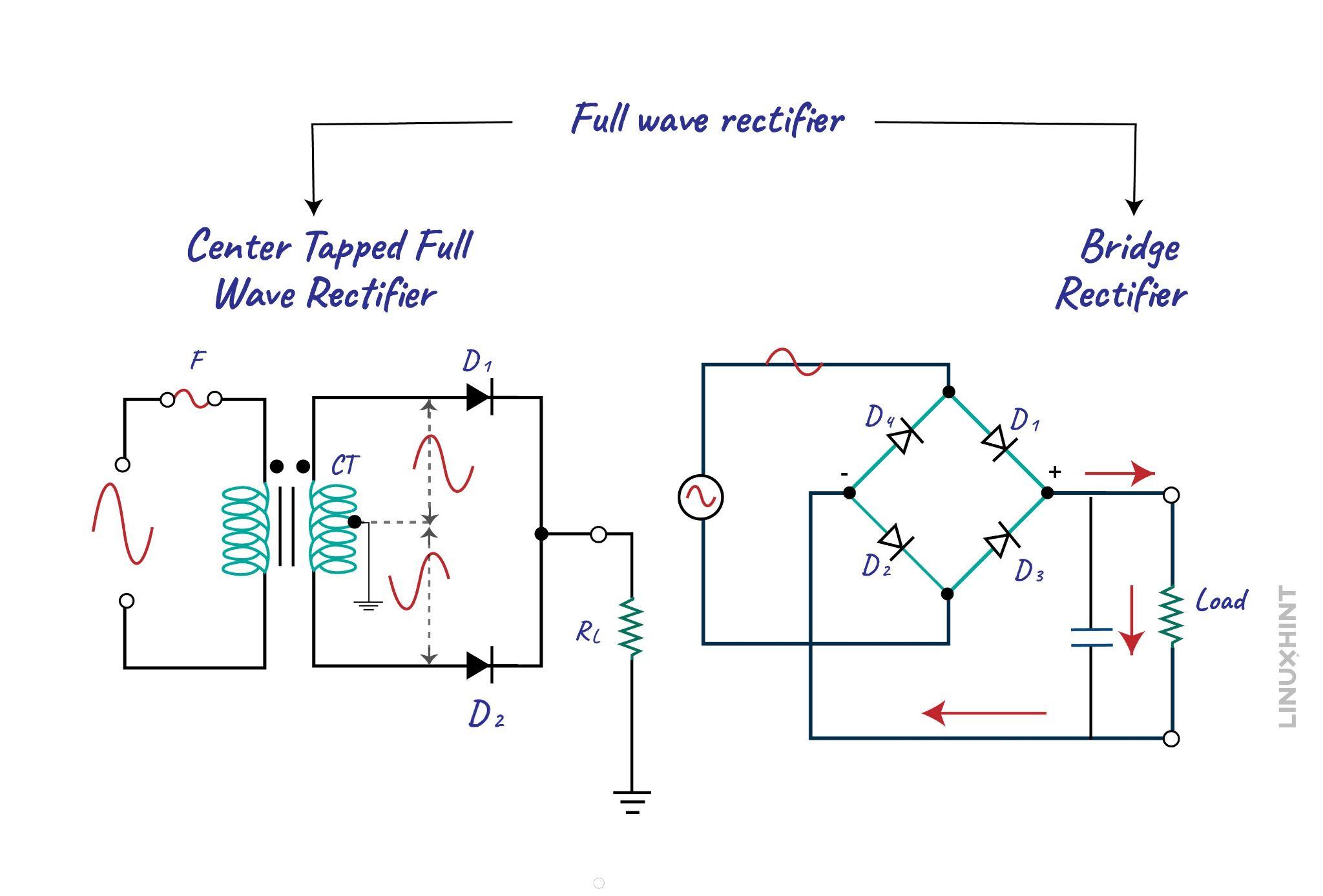
The full wave rectifier circuit having two diodes requires a transformer, so here is the circuit for the full wave rectifier circuit having two diodes:
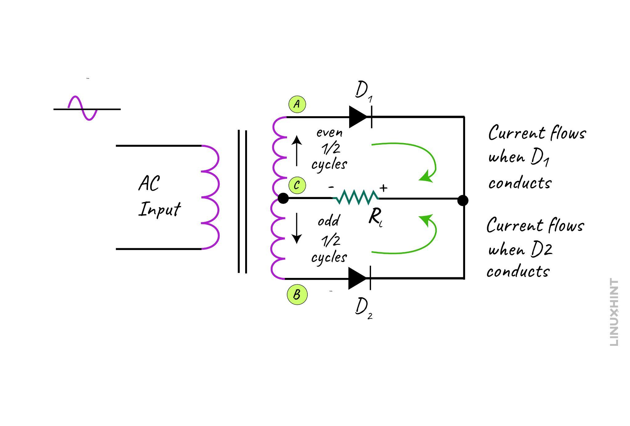
The diodes are connected across the load RL and when the point A has positive polarity with respect to point C, then the diode D1 will conduct as it will be in forward bias. However, when point B is on positive potential with respect to point C then diode D2 allows the flow of current, and this is how the full wave rectifier works. As a result of this behavior, the negative half of the AC supply is clipped, and a pure DC waveform is generated on the output.
In other words, the first diode conducts in the positive half cycle of the AC supply and the second diode is in reverse bias condition. Whereas in the negative half cycle, the second diode conducts and the first one remains reverse biased.
Full Wave Rectifier with a Capacitor Filter
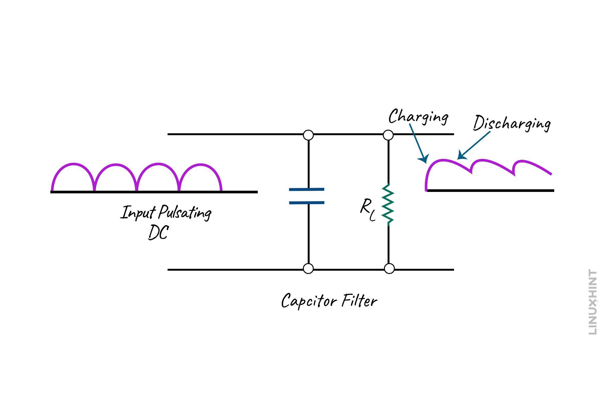
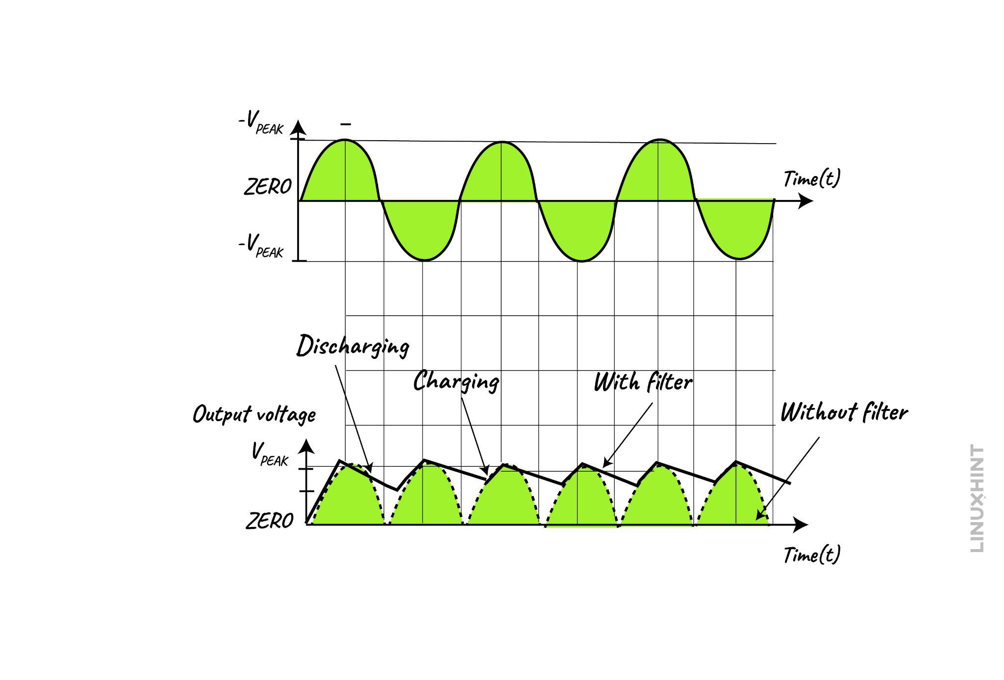
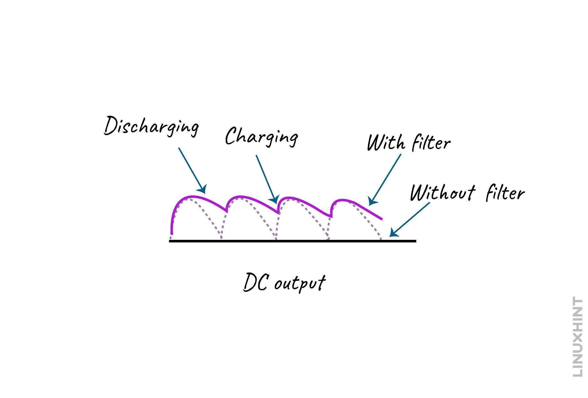
The DC output received from the full wave rectifier still contains some ripples which affect the quality of the signal. So, to filter out these ripples usually a capacitor is used which is connected in parallel with the connected load. Now the power supply is turned on and the capacitor starts to charge when the Diode D1 is in forward bias that is in the positive half cycle. In the negative half cycle, the capacitor starts discharging but is not completely discharged.
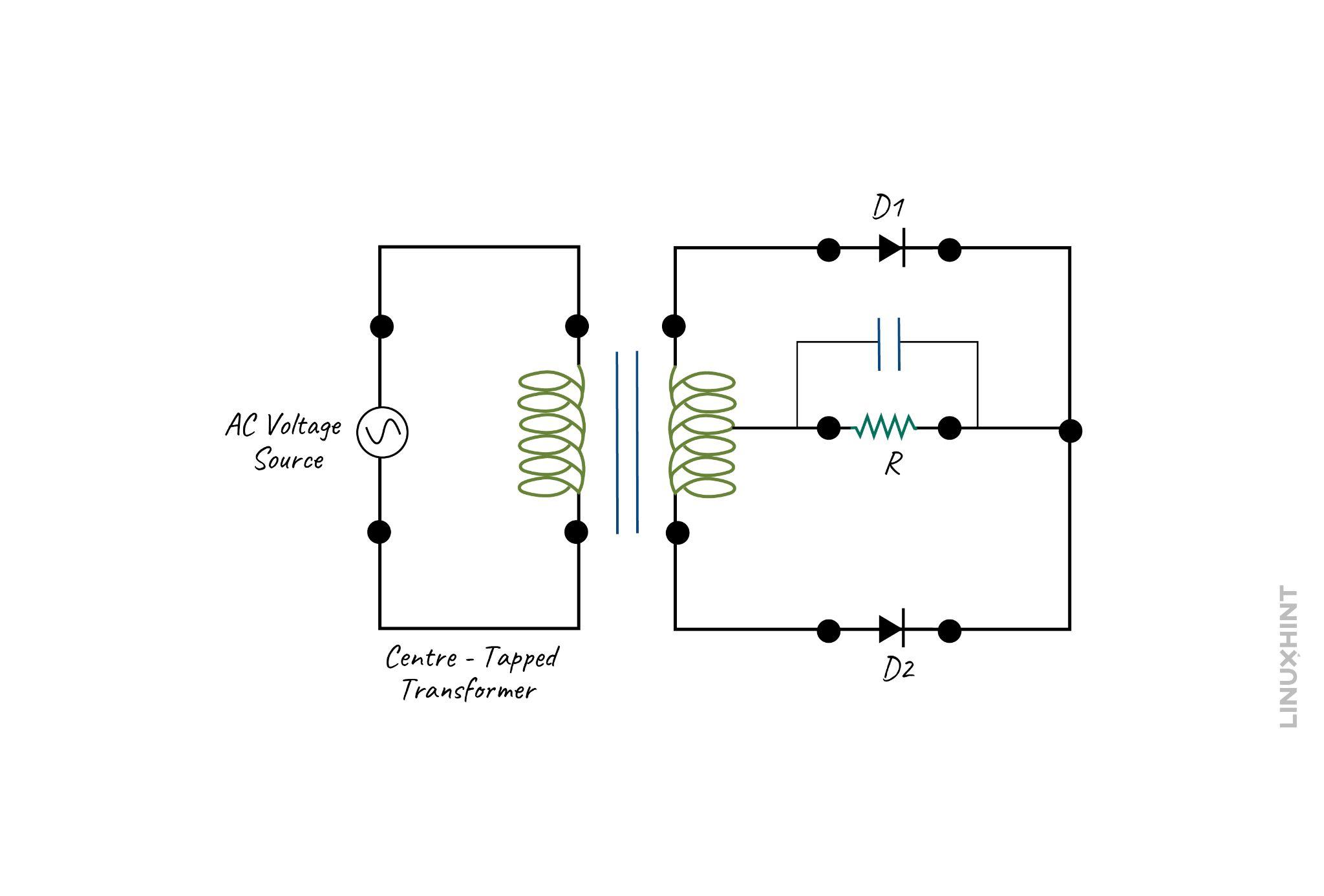
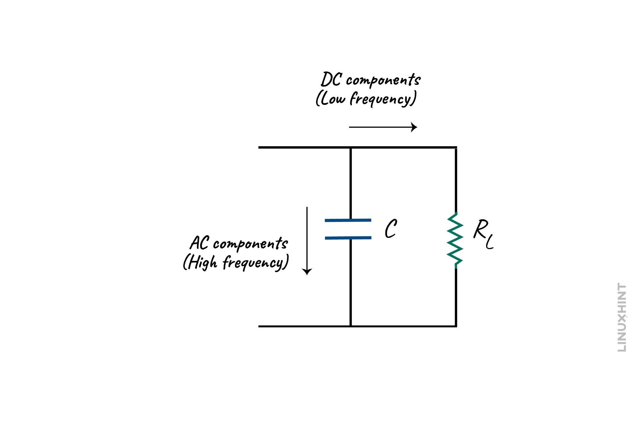
The output of the rectifier has both the AC and DC components and as we know the capacitors block the direct current. So, all the AC components in the rectifier output will pass through the capacitor, leaving a pure DC signal for the load:
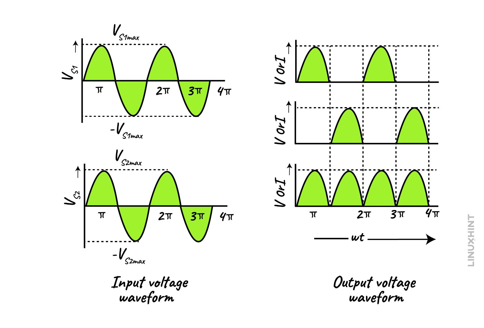
The final waveform for the rectifier output with the capacitor will be:
Full Wave Bridge Rectifier
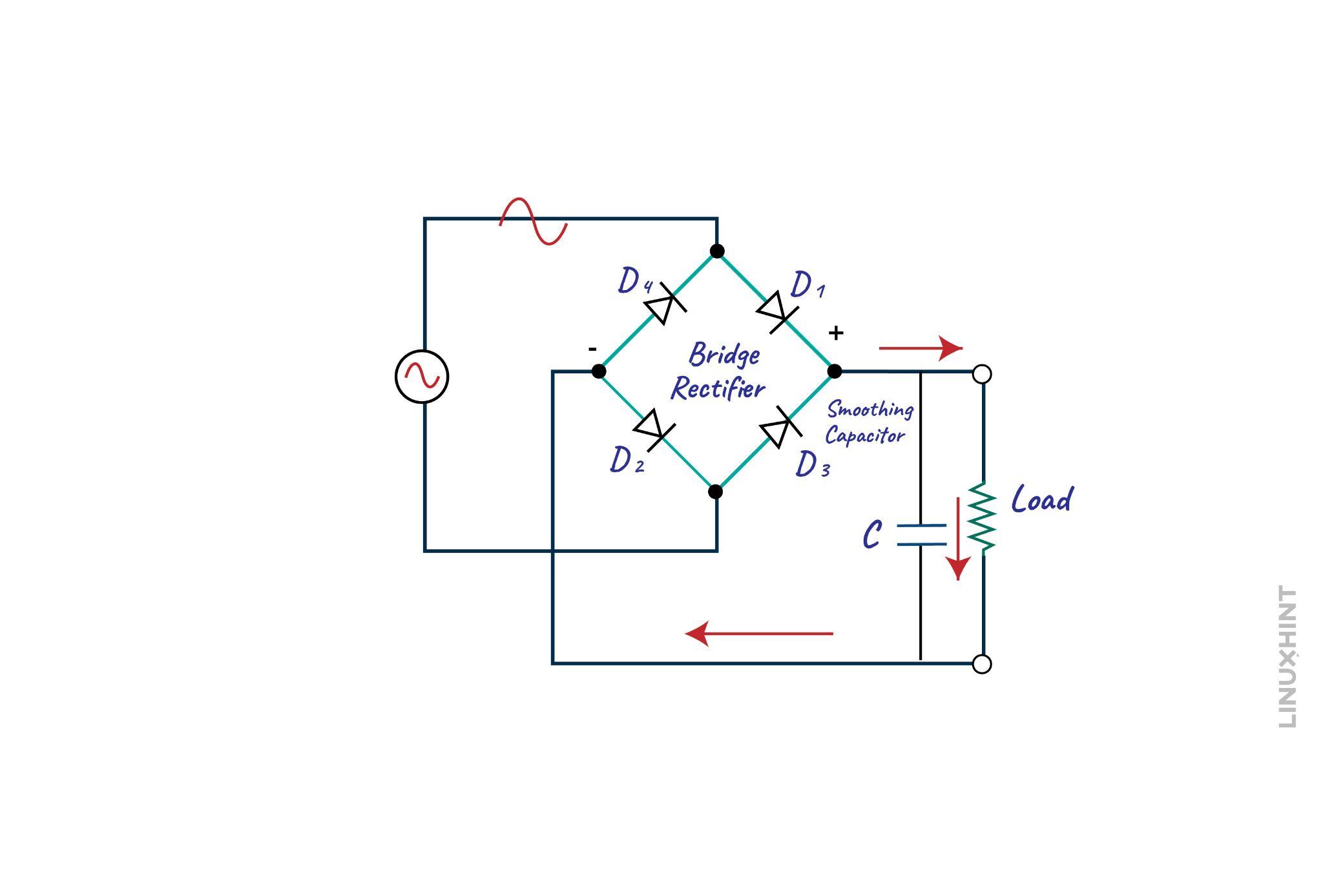
The full wave bridge rectifier comprises four diodes that are arranged in the form of a bridge. However, it doesn’t require a center tapped transformer which makes it less costly compared to the other type. The output of the bridge rectifier is almost the same as the center-tapped full-wave rectifier, the circuit of the full-wave bridge rectifier is given below:
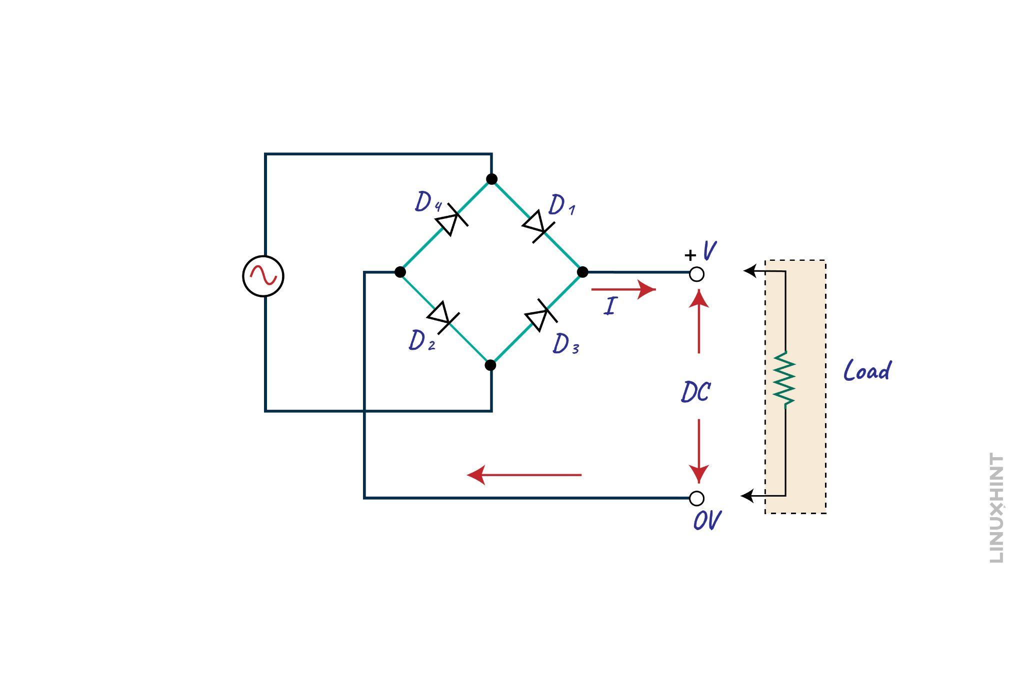
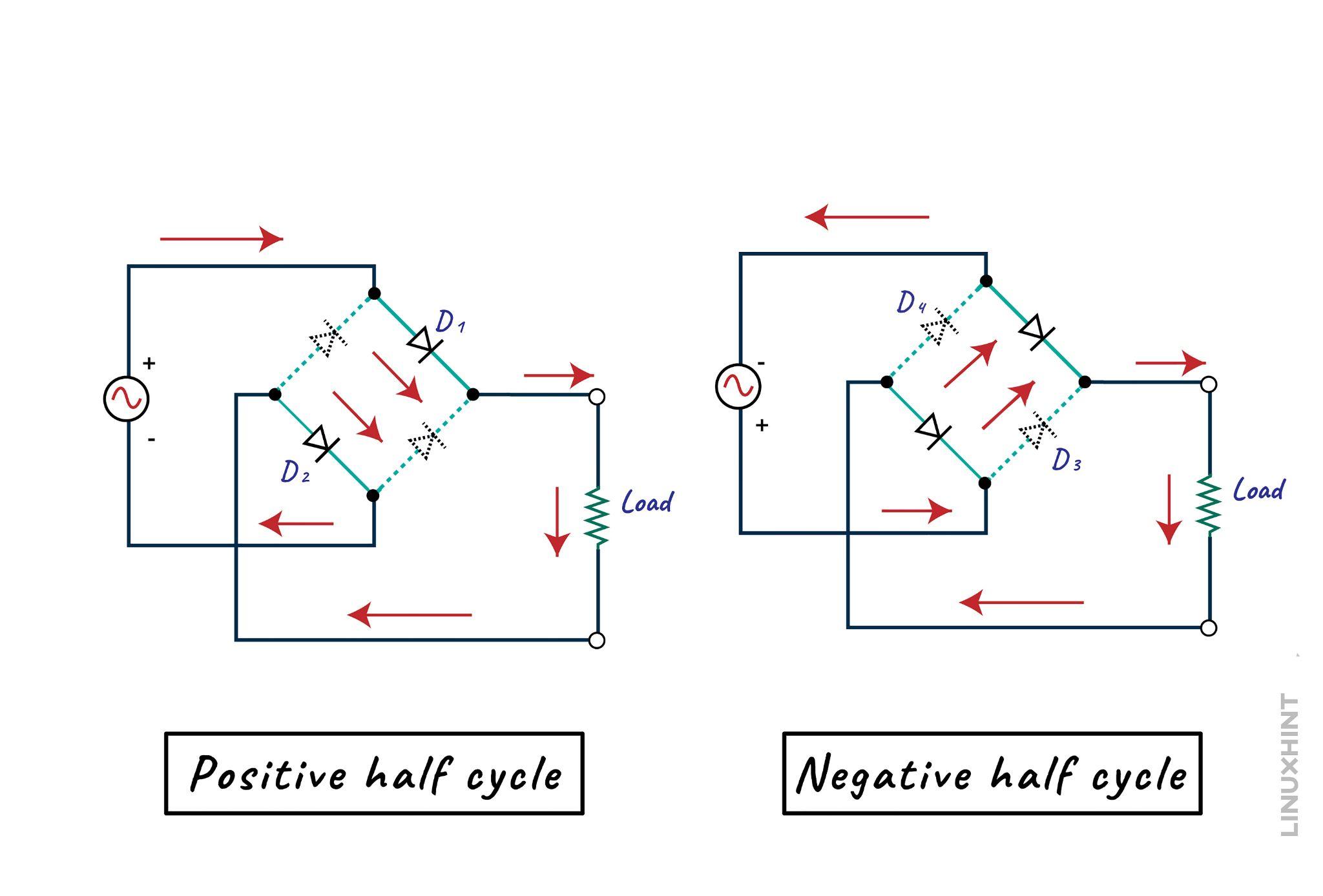
Here the diodes are in series with each other, and the two diodes will conduct during every half cycle, in the positive half cycle the diodes D1 and D2 will be forward biased, and the other two will be in a non-conducting state. However, in the negative half cycle, the other two diodes D3 and D4 will be in forward bias.
The full-wave bridge rectifier has a higher voltage drop as compared to the center-tapped transformer full-wave rectifier because there are two diodes in the conducting state for each cycle. Moreover, the peak inverse voltage of the bridge rectifier is equal to the voltage in the transformer on the secondary side, and thus it can be used in high-voltage applications. Since the working of both types of rectifier circuits is the same, the output waveform will be the same.
Bridge Rectifier with Capacitor Filter
Like the center-tapped transformer full wave rectifier, the capacitor in the bridge rectifier is connected in parallel with the load. This capacitor is also known as a smoothing capacitor, as it blocks the DC and allows the AC component of the signal to pass through it:
The function of the capacitor filter in a bridge rectifier is the same as that of a center-tapped full-wave rectifier, and the ripple factor for both types is the same. Therefore, the waveform will be the same once the smoothing capacitor is connected to the bridge rectifier. It is to be noted that if we select a capacitor with higher capacitance then the ripple factor is reduced further but the discharge voltage will be increased.
Difference Between Center Tapped Full Wave Rectifier and Bridge Rectifier
Although both circuits work in the same way and produce similar outputs still, there are some minor differences between the two:
| Rectifier Parameters | Bridge Rectifier | Center Tap Full Wave Rectifier |
| Peak Inverse Voltage | PIV=Vm | PIV=2Vm |
| Transformer Utilization factor | 0.812 | 0.693 |
| The voltage drops across the diode | High | Low |
| Center tapping | Not required | Required |
| Transformer KVA rating | Low | High |
| Ripple factor | 0.48 | 0.48 |
Conclusion
Capacitors are charge storage passive devices that are used for various applications, one of which is the filtration of any transients at the output of the circuits. In rectifier circuits, the capacitor is used for filtering out the ripples in their output which are in short, the AC components. Since the capacitors always block the DC, it will only allow the AC component to pass through it which will then travel to the ground.
The full wave rectifier is further divided into two types, one is with the center-tapped transformer while the other has a bridge of four diodes. So, the capacitor with both the full wave rectifier circuits will have the same behavior.
Source: linuxhint.com