Exploring Phasor Diagrams and Phasor Algebra in AC Circuits
Phasor Diagram
The graphical representation that gives the relationship between two or more electrical quantities in an AC circuit, using magnitude and direction, is called a phasor diagram.
A phasor is a line with an arrowhead on one end showing the direction of the electrical quantity, and the other end of the line is pivoted at a fixed point called the origin. The length of the phasor line represents the magnitude of the electrical quantity, such as voltage and current.
A phasor is a complex number that has both magnitude and angle, the diagram which gives the relationship between the magnitude and the angle of an electrical quantity is called a phasor diagram.
Phase Difference
It is known as the difference in the phase angles of two electrical quantities. On applying the AC voltage to an inductor, the voltage reaches its maximum value at 90o before the current starts to flow at zero degrees.
But in capacitors, voltage is directly proportional to the charge between the plates of the capacitor. The current must flow to build up the voltage across the two plates of the capacitor. The current reaches its maximum value at 90o. The phase difference between voltage and current in capacitors 90o and can be represented by a phasor diagram as:
Phasor Diagram of RLC circuit
Suppose that we have an RLC circuit in which a resistor, inductor, and capacitor are connected in series with an AC voltage supply as shown:
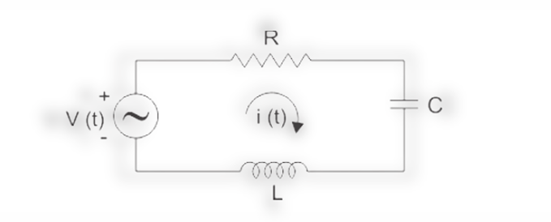
- All the resistors, inductors, and capacitors are connected in series, so the current will be the same in all of them. So, the current phasor for all the components will be drawn along the x-axis, and we will take it as a reference to other phasors.
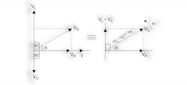
- In resistors both current and voltage are in the same phase. So, we draw the voltage VR along the same axis of the current phasor.
- In inductors, the voltage leads by 90 degrees with the current. The voltage phasor for inductor VL will be drawn perpendicular or at 90o to the current phasor.
- For capacitors, voltage lagged by 90 degrees from current. So the voltage phasor VC for the capacitor will be drawn below the current phasor axis at 90o.
Where:


And:
![]()
Phasor Diagram for 3-Phase
Three voltages are generated by connecting three identical coils, having the same number of turns, on a rotor shaft at an angle of 120o with each other. It consists of three sinusoidal voltages 120 degrees out of phase with one another.
The phasor diagram for the three-phase voltage supply can be drawn as:
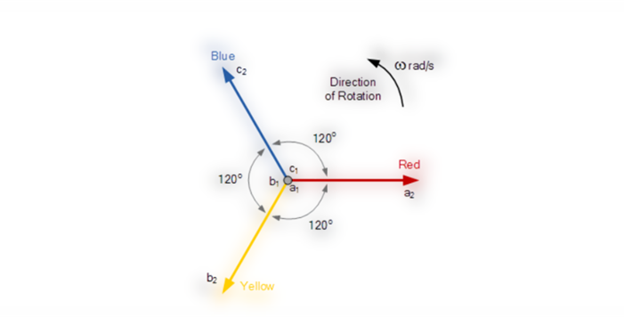
To identify each of the three phases, we use color codes red, yellow, and blue. The red one is taken as the reference phase of rotation. All three phasors rotate anti-clockwise direction with an angular speed of ω measured in radians per second. The sequence for rotation in three-phase is red to yellow and yellow to blue.
Voltage Equations for 3-Phase
Taking the red phase as a reference, the voltage equation for all three phases is as follows.
For red phase:

For yellow phase:

And for the blue phase:

Or:

Phasor Algebra
Phasor algebra is the application of mathematical operations like addition, subtraction, multiplication, and division to the phasors of various electrical quantities. With the help of phasor algebra, we can convert complex electrical circuits into simple algebraic equations and can easily solve them.
Phasor Addition
To add two or more phasors of electrical quantity, we have to split them into real and imaginary parts and add them separately. If the two phasors are in phase, then they can be added directly. For example, if V1 = 25V and V2 = 40V are in the same phase. We will simply add them directly and get the result V = V1 + V2 = 65V.
If two or more phasors are not in phase, for example, In an AC circuit two voltages across the two electrical components are as V1 = 10V and V2 = 20V and Voltage V1 leads the voltage V2 by 60o.
Horizontal and vertical components of voltage V1 are:
![]()
![]()
So:
![]()
Similarly, the horizontal and vertical components of voltage V2 are as:
![]()

So:
![]()
Now:


The magnitude of the resultant vector VT will be given by the resultant vector of V1 and V2.


![]()
Phasor Subtraction
Phasor subtraction is very similar to phasor addition:


Phasor Multiplication
Phasor multiplication can be done by using a polar form of vectors. V1 and V2 are vectors with phase angles θ1 and θ2 then:
![]()
![]()
And:
![]()
The phase angle of the resultant phasor will be given as:

Phasor Division
As phasor multiplication, phasor division is carried out by polar of two phasors. For illustration, if V1 and V2 are vectors with phase angles θ1 and θ2 then:
In polar form, we have:

![]()
The phasor resultant of two voltages will be as:

The phase angle of the phasor resultant can be found by:
![]()
Conclusion
The graphical representation of the relationship between two or more electrical quantities in an AC circuit using magnitude and direction is known as a phasor diagram. A phasor is a line with an arrowhead showing the direction and the length of the phasor is proportional to the magnitude of the electrical quantity. The other end of the phasor line is fixed to a point called the origin of the axis.
Source: linuxhint.com