ESP32 with PIR Motion Sensor using Interrupts and Timers – Arduino IDE
ESP32 is an IoT based microcontroller board which can be used to interface, control and read different sensors. PIR or motion sensor is one of the devices we can interface with ESP32 to detect movement of an object in the range of motion sensor using ESP32.
Before we start interfacing ESP32 with PIR sensor we must know how interrupts work and how to read and handle them in ESP32. Next we must understand the core concept of delay() and millis() function in ESP32 programming.
Let’s discuss the working of PIR with ESP32 in detail.
Here is the content for this article:
1: What Are Interrupts
Most of the events that happen in ESP32 programming run sequentially which means line by line execution of code. To handle and control the events that don’t need to run during sequential execution of code an Interrupts are used.
For example, if we want to execute a certain task when any special event occurs, or a trigger signal is given to digital pins of the microcontroller we use interrupt.
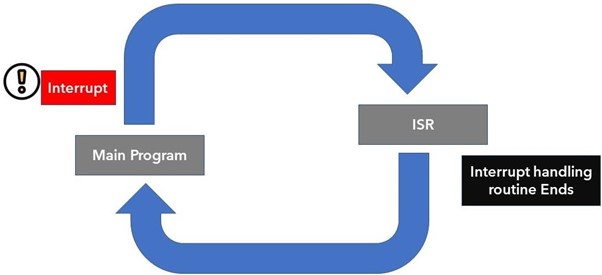
With interruption we don’t need to continuously check the digital state of the ESP32 input pin. When an interrupt occurs the processor halts the main program and a new function is called which is known as ISR (Interrupt Service Routine). This ISR function handles the interrupt caused after that return back to the main program and start executing it. One of the examples of ISR is PIR motion sensor which generates an interrupt once motion is detected.
1.1: Interrupts Pins in ESP32
An external or hardware interrupt can be caused by any hardware module such as touch sensor or push button. Touch interrupts happen when a touch is detected at ESP32 pins or GPIO interrupt can also be used when a key or push button is pressed.
In this article we will trigger an interrupt when the motion is detected using the PIR sensor with ESP32.
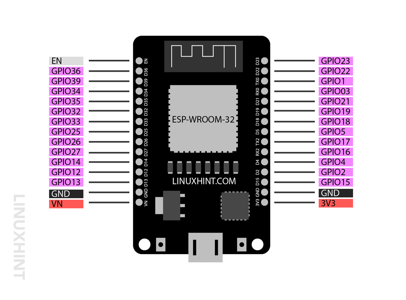
Almost all the GPIO pins except 6 SPI integrated pins which usually come in the 36-pin version of ESP32 board cannot be used for the purpose of interrupt calling. So, to receive the external interrupt following are the pins highlighted in purple color one can use in ESP32:
This image is of a 30 pin ESP32.
1.2: Calling an Interrupt in ESP32
For using interrupt in ESP32 we can call attachInterrupt() function.
This function accepts following three arguments:
-
- GPIO pin
- Function to be executed
- Mode
1: GPIO pin is the first argument called inside the attachInterrupt() function. For example, to use digital pin 12 as an interrupt source we can call it using digitalPinToInterrupt(12) function.
2: Function to be executed is the program executed every time once the interrupt is reached or triggered by an external or internal source. It can be either blinking an LED or turning a fire alarm.
3: Mode is the third and last argument the interrupt function needs. It describes when to trigger the interrupt. Following are the modes can be used:
-
- Low: Trigger the interrupt every time the defined GPIO pin is low.
- High: Trigger the interrupt every time the defined GPIO pin is high.
- Change: Trigger interrupt every time GPIO pin changes its value from high to low or vice versa.
- Falling: It is the mode to trigger an interrupt when a certain pin starts falling from high state to low.
- Rising: It is the mode to trigger an interrupt when a certain pin starts rising from low state to high.
Today we will be using Rising mode as a third argument for the interrupt function whenever the PIR sensor detects the interrupt LED or sensor will light up because it goes from low state to high.
2: Timers in ESP32 Programming
Timers in microcontroller programming play a significant role for executing instructions for a specific timer period or at specific instance of time.
Two main functions commonly used to trigger the output are delay() and millis(). The difference between both of them as delay() function stops the rest of the program once it starts executing while millis() runs for the defined period of time then the program goes back to main functions.
Here we will be using a LED with PIR sensor and we don’t want to glow it continuously after an interrupt triggers. We will be using millis() function that allows us to glow it for some defined time and then again goes back to the original program once that time stamp passes.
2.1: delay() Function
delay() function is pretty simple it only takes one argument which is ms of unsigned long data type. This argument represents the time in milliseconds we want to pause the program until it moves to the next line.
For example, the following function will stop the program for 1 sec.
delay() is a kind of blocking function for microcontrollers programming. delay() blocks the rest of the code to execute until this particular function times don’t complete. If we want to execute multiple instructions, we should avoid using delay functions instead we can use millis or external timer RTC modules.
2.2: millis() Function
millis() function returns the number of milliseconds passed since ESP32 board started running the current program. By writing a few lines of code we can easily calculate the present time at any instance while running the ESP32 code.
millis is widely used where we need to run multiple tasks without blocking the rest of the code. Here is the syntax of the millis function used for calculating how much time passed so we can execute a specific instruction.
previousMillis = currentMillis;
}
This code subtracts the previous millis() from current millis() if the subtracted time equals to define the interval a specific instruction will be executed. Let’s say we want to blink an LED for 10 sec. After every 5 minutes we can set the time interval equal to 5 minutes (300000ms). The code will check for the interval every time the code runs, once it reaches it will blink the LED for 10 sec.
Note: Here we will be using millis() function for interfacing ESP32 with PIR sensor. The main reason behind using milli and not delay is that the millis() function does not block the code as delay() function did. So once the PIR detects motion an interrupt will be generated. Using the interrupt millis() function will trigger the LED for defined time after that if the motion is stopped millis() function will reset and wait for the next interrupt.
In case if we used delay() function it will completely block the code and any interrupt caused will not be read by ESP32 resulting in failure of the project.
3: Interfacing PIR Sensor with ESP32
Here we will be using millis() function in Arduino IDE code because we want to trigger LED every time the PIR sensor detects some movement. This LED will glow for a set time after that it will go back to normal condition.
Here is a list of components we will be required:
-
- ESP32 development board
- PIR motion sensor (HC-SR501)
- LED
- 330 Ohm resistor
- Connecting wires
- Breadboard
Schematic for PIR sensor with ESP32:
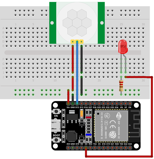
Pin connections of ESP32 with PIR sensor is:
| ESP32 | PIR Sensor |
| Vin | Vcc |
| GPIO13 | OUT |
| GND | GND |
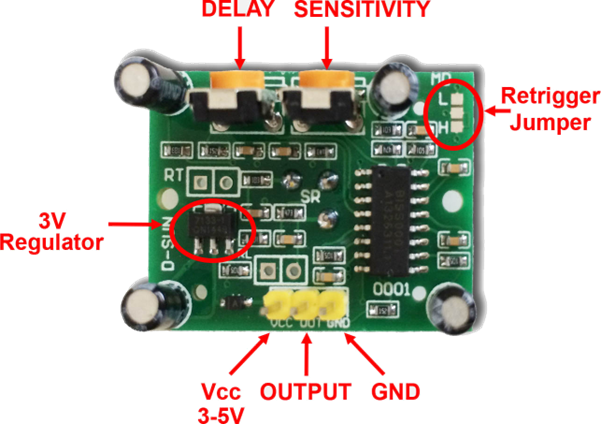
3.1: PIR Motion Sensor (HC-SR501)
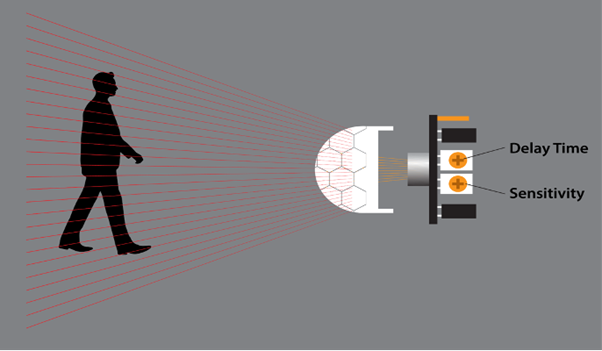
PIR is an acronym for passive infrared sensor. It uses a pair of pyroelectric sensors that detect heat around its surroundings. Both these pyroelectric sensors lie one after another and when an object comes inside their range a change in heat energy or the signal difference between both these sensors causes the PIR sensor output to be LOW. Once the PIR out pin goes LOW, we can set a specific instruction to execute.
Following is the characteristics of PIR sensor:
-
- Sensitivity can be set depending upon the location of the project (such as sensing mouse or leaf movement).
- PIR sensor can be set for how long it detects an object.
- Widely used in home security alarms and other thermal based movement detection applications.
3.2: Pinout HC-SR501
PIR HC-SR501 comes with three pins. Two of them are power pins for Vcc and GND and one is the output pin for the trigger signal.
Following is the description of PIR sensor pins:
| Pin | Name | Description |
| 1 | Vcc | Input pin for sensor Connect to ESP32 Vin Pin |
| 2 | OUT | Sensor Output |
| 3 | GND | Sensor GND |
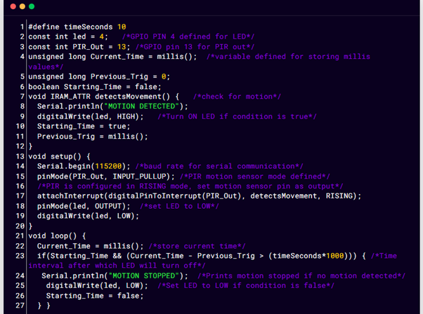
3.3: Code
Now to program ESP32 write the given code in Arduino IDE editor and upload it to ESP32.
const int led = 4; /*GPIO PIN 4 defined for LED*/
const int PIR_Out = 13; /*GPIO pin 13 for PIR out*/
unsigned long Current_Time = millis(); /*variable defined for storing millis values*/
unsigned long Previous_Trig = 0;
boolean Starting_Time = false;
void IRAM_ATTR detectsMovement() { /*check for motion*/
Serial.println("MOTION DETECTED");
digitalWrite(led, HIGH); /*Turn ON LED if condition is true*/
Starting_Time = true;
Previous_Trig = millis();
}
void setup() {
Serial.begin(115200); /*baud rate for serial communication*/
pinMode(PIR_Out, INPUT_PULLUP); /*PIR motion sensor mode defined*/
/*PIR is configured in RISING mode, set motion sensor pin as output*/
attachInterrupt(digitalPinToInterrupt(PIR_Out), detectsMovement, RISING);
pinMode(led, OUTPUT); /*set LED to LOW*/
digitalWrite(led, LOW);
}
void loop() {
Current_Time = millis(); /*store current time*/
if(Starting_Time && (Current_Time – Previous_Trig > (timeSeconds*1000))) { /*Time interval after which LED will turn off*/
Serial.println("MOTION STOPPED"); /*Prints motion stopped if no motion detected*/
digitalWrite(led, LOW); /*Set LED to LOW if condition is false*/
Starting_Time = false;
}
}
The code started by defining GPIO pins for LED and PIR output. Next, we created three different variables that will help to turn on LED when motion is detected.
These three Variables are Current_Time, Previous_Trig, and Starting_Time. These variables will store the current time, time at which motion is detected and timer after the motion is detected.
In the setup part first, we defined serial baud rate for communication. Next using pinMode() set the PIR motion sensor as INPUT PULLUP. To set the PIR interrupt attachInterrupt() is described. GPIO 13 is described to detect movement on RISING mode.
Next in loop() part of the code, using the millis() function we turned ON and OFF the LED when a trigger is achieved.
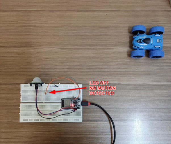
3.4: Output
In the output section we can see the object is out of range of the PIR sensor, so the LED is turned OFF.
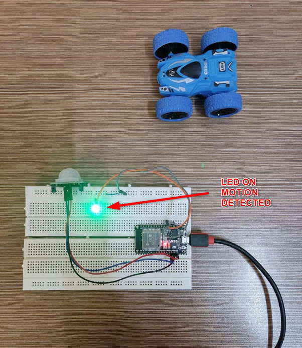
Now the motion detected by the PIR sensor LED will turn ON for 10 sec after that if no motion is detected it will remain OFF until the next trigger is received.
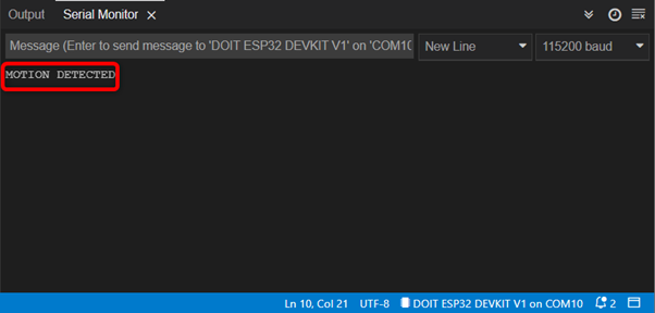
Following output is shown by the serial monitor in Arduino IDE.
Conclusion
A PIR sensor with ESP32 can help to detect motion of objects passing through its range. Using the interrupt function in ESP32 programming we can trigger a response at some specific GPIO pin. When change is detected the interrupt function will be triggered and a LED will turn ON.
Source: linuxhint.com