ESP32 PWM with MicroPython Using Thonny IDE
PWM Pins in ESP32
The ESP32 board has 16 independent channels that can generate PWM signals having different time periods and width. Almost all of the GPIO pins that can act as output can be used to generate a PWM signal. GPIO pins 34,35,36,39 can not be used as PWM pins as they are input only pins.
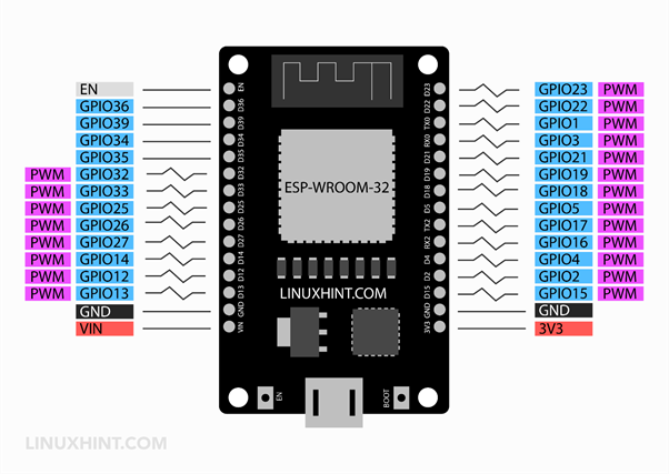
However, in the 36 pins variant of ESP32 board the six SPI integrated pins are also not recommended to use as PWM signal generators.
How to Use ESP32 PWM Pins
PWM is a technique to control output using a variable digital pulse signal. PWM helps in controlling motor speed or LED brightness. Main component in generating PWM signals is the internal timer module. Timer is controlled by the internal microcontroller clock source.
As time starts, its value is compared with two comparators and once it reaches the defined Duty cycle value a signal at PWM pin is triggered which changes pin states to LOW. Next the timer signal goes on counting till it achieves the Period register value. Now again the comparator will generate a new trigger and PWM pins state shift from LOW to HIGH.
To generate a PWM signal at GPIO pins the following four characteristics must be defined:
- PWM Frequency: Frequency for PWM is opposite to the time period. Any value can be set depending upon application.
- PWM Resolution: Resolution defines the number of discrete levels of duty cycle we can control.
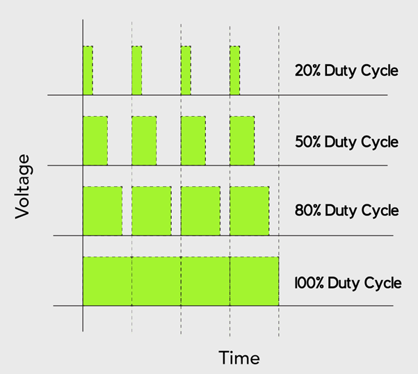
- Duty Cycle: Amount of time during which a PWM signal is in active state.
- GPIO pin: Pin number of ESP32 where PWM signal is to be read. (GPIO 34,35,36,39 cannot be used)
Here are some points which one needs to keep in mind while configuring ESP32 PWM signal:
- Total of 16 independent PWM Channels are in ESP32 which are divided into two groups each group having 8 channels.
- 8 PWM channels are high speed while the other 8 channels are LOW.
- PWM resolution can be set between 1-bit and 16-bits.
- PWM frequency is dependent upon the resolution of PWM.
- Duty cycle can be automatically increased or decreased without processor intervention.
Controlling LED Brightness Using PWM Signal in ESP32
Now we will control LED brightness using a PWM signal. Connect LED with ESP32 GPIO pin 18.
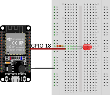
Below table shows pin configuration for LED with ESP32.
| ESP32 GPIO Pin | LED |
|---|---|
| GPIO 18 | +ive |
| GND | -ive |
Code for Single LED Brightness Control
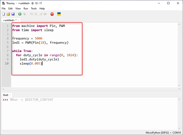
To program an ESP32 board with MicroPython open Thonny IDE and upload the below given code. Remember to flash ESP32 board with MicroPython firmware if using for the first time.
from time import sleep
frequency = 5000
led1 = PWM(Pin(18), frequency)
while True:
for duty_cycle in range(0, 1024):
led1.duty(duty_cycle)
sleep(0.005)
Code started by importing the required classes.
The LED object is initialized for the PWM signal.
A PWM object needs two arguments: one is frequency and other one is duty cycle.
Frequency: Frequency value ranges from 0 to 78125. Here we used a frequency of 5KHz to control the LED brightness.
Duty Cycle: Its value ranges from 0 and 1023. Here 1023 is equal to maximum value which defines 100% duty cycle and full brightness of LED and similarly on opposite side, 0 corresponds to 0% duty cycle means LED will be completely dim.
Using the duty cycle function duty() we pass the duty cycle as an argument to this function.
Inside the while loop a for loop is initialized that increments the duty cycle every time it runs by 1 with an interval equal to 5 ms.
led.duty(duty_cycle)
sleep(0.005)
The range() function can be written as:
Here start specifies the duty cycle starting value which is equal to 0. stop explaining the value we want to stop the duty cycle. Here we have used the value 1024 because the maximum value where it can come is 1023 and we are incrementing 1 in this value after every loop.
The Last step describes the incrementing factor and by default it is 1.
Output
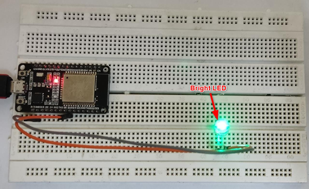
On hardware we can see the brightness of the LED at its full, this means the duty cycle signal is at 1024.
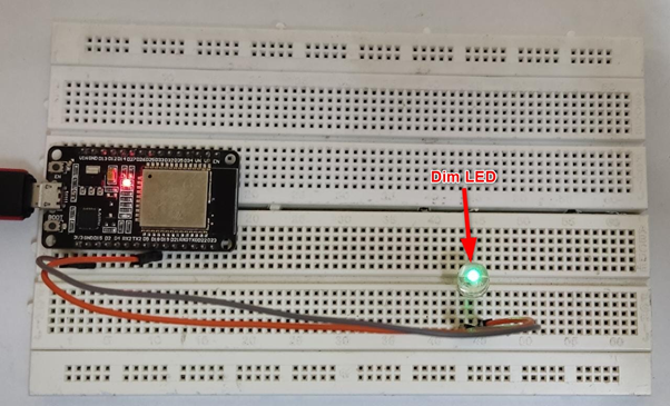
Now we can see the LED is completely dim, which means the duty cycle value is at 0.
Controlling Multiple Pins with Same PWM Signal
We can control multiple pins with the same PWM signal which is generated from a single PWM channel. Now we will modify the single LED example to control multiple LEDs brightness.
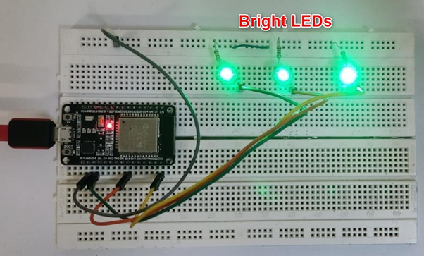
Connect three LEDs at GPIO pins 23 ,18 and 15.
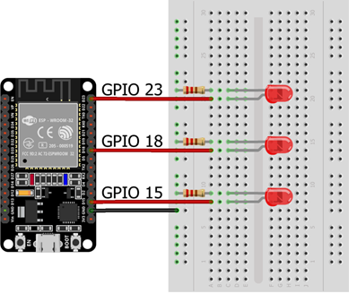
Below table gives us pin layout for three LEDs.
| ESP32 GPIO Pin | LED |
|---|---|
| GPIO 23 | +ive LED 1 |
| GPIO 18 | +ive LED 2 |
| GPIO 15 | +ive LED 3 |
| GND | LED common GND |
Code for Multiple LEDs Brightness Control
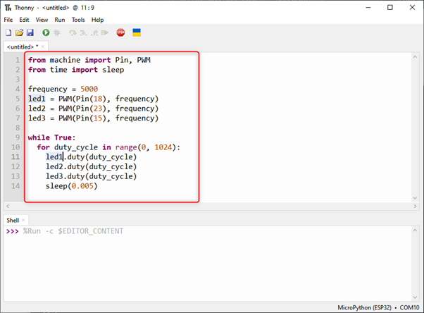
Open Thonny IDE and write the code in the editor window. After that, connect the ESP32 board and upload it.
from time import sleep
frequency = 5000
led1 = PWM(Pin(18), frequency)
led2 = PWM(Pin(23), frequency)
led3 = PWM(Pin(15), frequency)
while True:
for duty_cycle in range(0, 1024):
led1.duty(duty_cycle)
led2.duty(duty_cycle)
led3.duty(duty_cycle)
sleep(0.005)
Code is similar to the previous example. We just added two new LEDs at GPIO pin 23 and 15.
Same duty cycle and frequency value is used.
Output
In the output section we can see that all three LEDs are at full brightness meaning all of them are receiving duty cycle having value 1024.
Now all three LEDs are dim meaning all of them have the same duty cycle coming from the same PWM channel having duty cycle value 0.
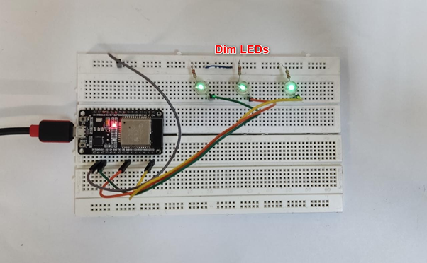
We have successfully controlled LED brightness using the PWM signal.
Conclusion
In this guide, we have discussed ESP32 PWM pins and how they can be used for controlling devices. We also discussed the code for controlling single and multiple LEDs using the PWM channel. Using this guide any type of hardware can be controlled with the help of PWM signal.
Source: linuxhint.com