ESP32 ADC – Read Analog Values with Arduino IDE
ESP32 ADC Introduction
The ESP32 board has two integrated 12-bit ADCs also known as SAR (Successive Approximation Registers) ADCs. The ESP32 board ADCs support 18 different analog input channels which means we can connect 18 different analog sensors to take input from them.
But this is not the case here; these analog channels are divided into two categories channel 1 and channel 2, both these channels have some pins that are not always available for ADC input. Let’s see what those ADC pins are along with others.
ESP32 ADC Pins
As mentioned earlier the ESP32 board has 18 ADC channels. Out of 18 only 15 are available in the DEVKIT V1 DOIT board having a total of 30 GPIOs.
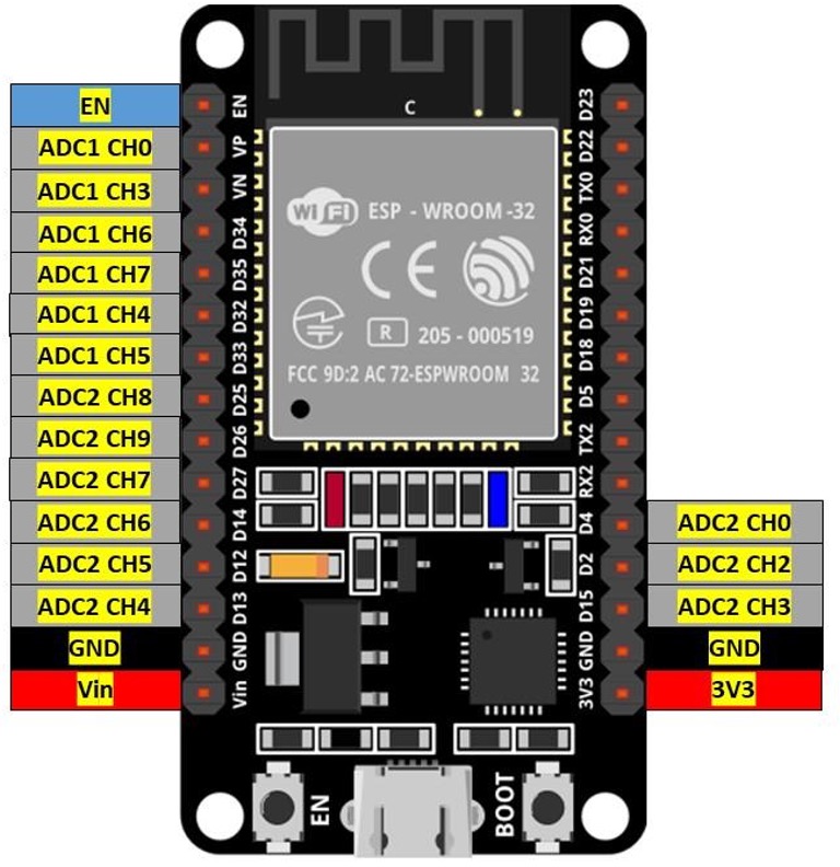
Look on to your board and identify the ADC pins as we highlighted them in the image below:
Channel 1 ADC Pins
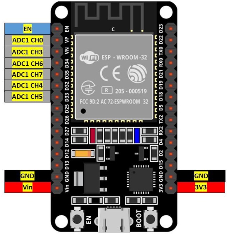
Following is the given pin mapping of ESP32 DEVKIT DOIT board. ADC1 in ESP32 has 8 channels however the DOIT DEVKIT board only supports 6 channels. But I guarantee these are still more than enough.
| ADC1 | GPIO PIN ESP32 |
|---|---|
| CH0 | 36 |
| CH1 | NA in 30 pin version ESP32 (Devkit DOIT) |
| CH2 | NA |
| CH3 | 39 |
| CH4 | 32 |
| CH5 | 33 |
| CH6 | 34 |
| CH7 | 35 |
Following image show ESP32 ADC1 channels:
Channel 2 ADC Pins
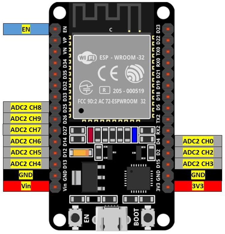
DEVKIT DOIT boards have 10 analog channels in ADC2. Although ADC2 has 10 analog channels to read analog data, these channels are not always available to use. ADC2 is shared with onboard WiFi drivers, which means at the time the board is using WIFI these ADC2 will not be available. Solution to this problem is to use ADC2 only when the Wi-Fi driver is off.
Below image shows pin mapping of ADC2 channel.
How to Use ESP32 ADC
ESP32 ADC works in a similar way like Arduino only difference here is it has 12 bit ADC. So, the ESP32 board maps the analog voltage values ranging from 0 to 4095 in digital discrete values.
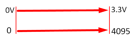
- If voltage given to ESP32 ADC is zero an ADC channel the digital value will be zero.
- If the voltage given to ADC is maximum means 3.3V the output digital value will be equal to 4095.
- To measure higher voltage, we can use the voltage divider method.
Note: ESP32 ADC is by default set at 12-bits, however it’s possible to configure it into 0-bit,10-bit, and 11-bit. The 12-bit default ADC can measure value 2^12=4096 and the analog voltage ranges from 0V to 3.3V.
ADC Limitation on ESP32
Here are some limitations of ESP32 ADC:
- ESP32 ADC cannot directly measure voltage greater than 3.3V.
- When Wi-Fi drivers are enabled ADC2 cannot be used. Only 8 channels of ADC1 can be used.
- The ESP32 ADC is not very linear; it shows non-linearity behavior and cannot distinguish between 3.2V and 3.3V. However, it is possible to calibrate ESP32 ADC. Here is an article that will guide you to calibrate ESP32 ADC nonlinearity behavior.
Nonlinearity behavior of ESP32 can be seen on the serial monitor of Arduino IDE.
Program ESP32 ADC Using Arduino IDE
Best way of understanding the working of ESP32 ADC is to take a potentiometer and read values against zero resistance to maximum. Following is the given circuit image of ESP32 with potentiometer.
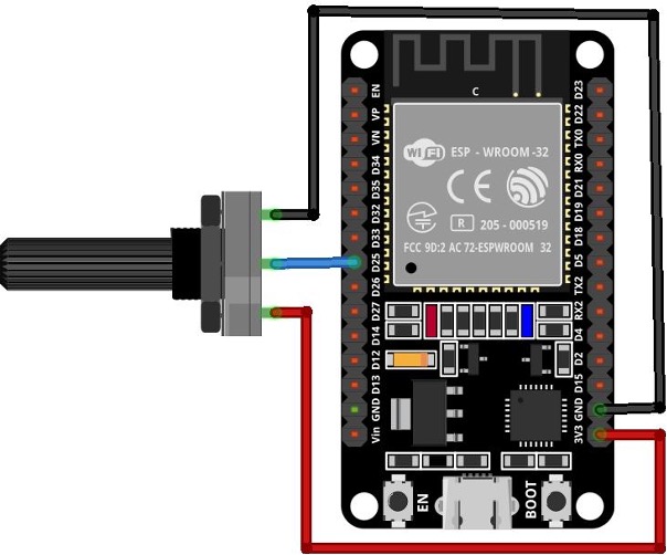
Connect the middle pin of potentiometer with digital pin 25 of ESP32 and 2 terminal pins with 3.3V and GND pin respectively.
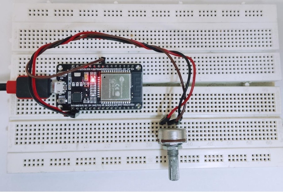
Hardware
Following image displays the hardware of ESP32 with potentiometer. Following is the list of components needed:
- ESP32 DEVKIT DOIT board
- Potentiometer
- Breadboard
- Jumper wires
Code
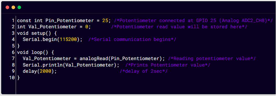
Open Arduino IDE and upload the below code in ESP32 board. To check how to install and configure ESP32 with Arduino IDE click here.
int Val_Potentiometer = 0; /*Potentiometer read value will be stored here*/
void setup() {
Serial.begin(115200); /*Serial communication begins*/
}
void loop() {
Val_Potentiometer = analogRead(Pin_Potentiometer); /*Reading potentiometer value*/
Serial.println(Val_Potentiometer); /*Prints Potentiometer value*/
delay(2000); /*delay of 2sec*/
}
Here in the above code, we initialize digital pin 25 for potentiometer on ESP32 board. Next to take input a variable Val_Potentiometer is initialized. Next Serial communication is initiated by defining baud rate.
In the loop part of code using analogRead() function ADC values will be read on pin 25 of ESP32. Next using Serial.print() all values are printed on the serial monitor.
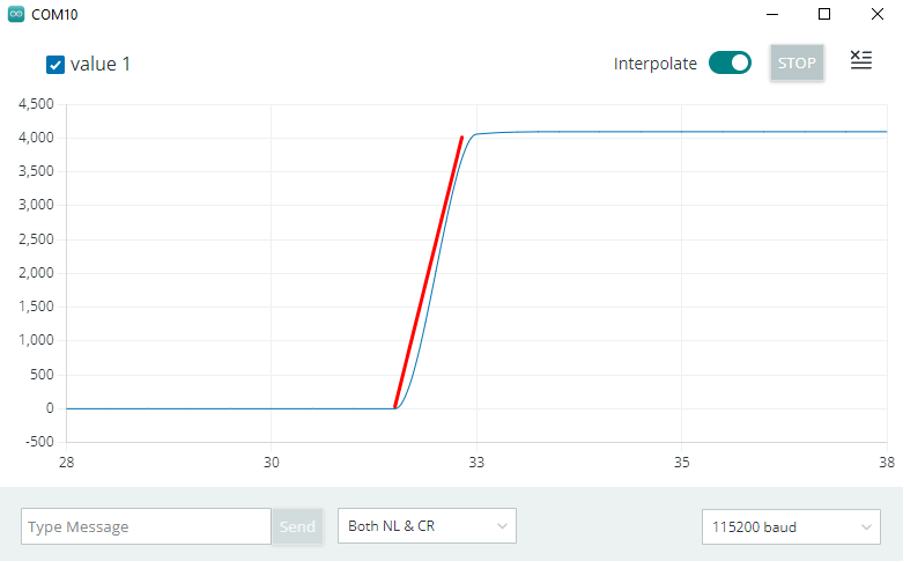
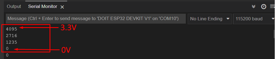
Output
Output displays analog values mapped against digital discrete values. When the read voltage is maximum that is 3.3V digital output is equal to 4095 and when the read voltage is 0V the digital output becomes 0.
Conclusion
Analog to digital converters is used everywhere especially when we have to interface microcontroller boards with analog sensors and hardware. ESP32 has two channels for ADC that are ADC1 and ADC2. These two channels combine to provide 18 pins for interfacing analog sensors. However, 3 of them are not available on the ESP32 30 pin version. To see more about reading analog values read the article.
Source: linuxhint.com