Digital Logic Gates | Tutorial
Basic Logic Gates
Boolean functions can be expressed fundamentally as sums of products or products of sums. Therefore, the fundamental gates are utilized for these fundamental operations. These gates are OR gate, NOT and AND gates.
AND gate
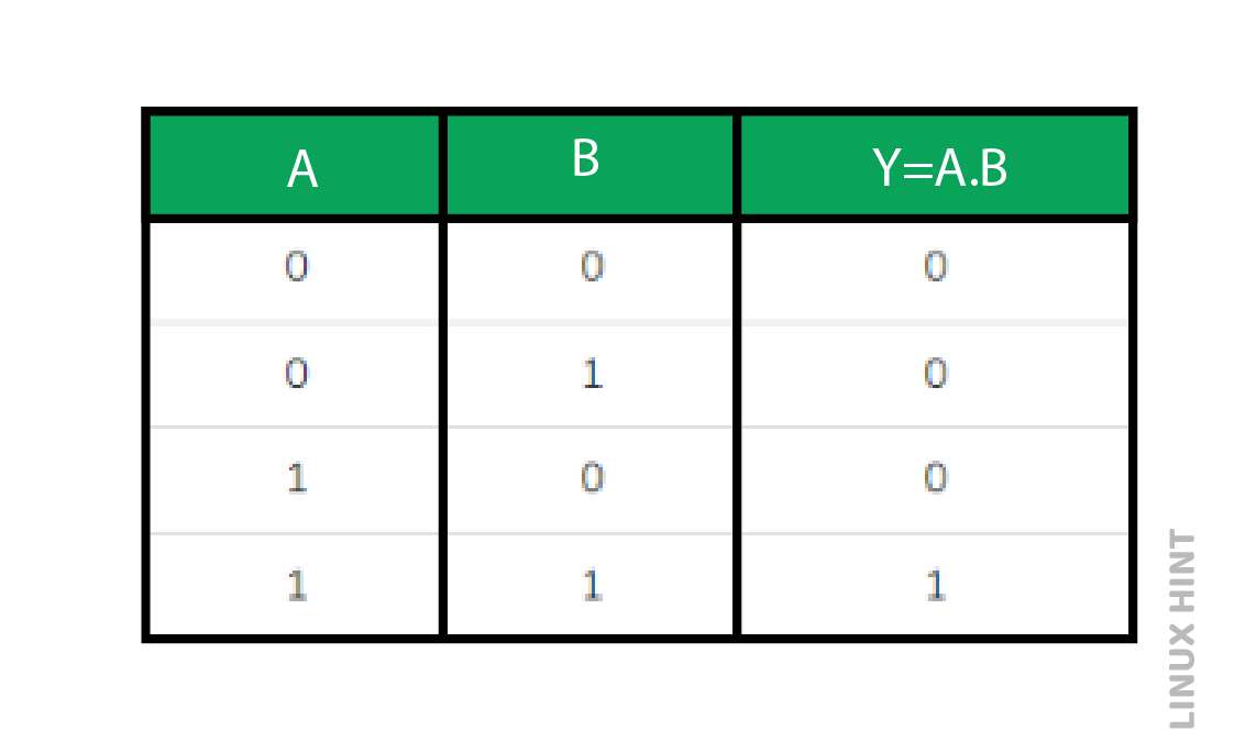
A digital circuit known as an AND gate generates an output that is the logical multiplication of its inputs if it has two or more inputs. The use of the “.” symbolizes the logical AND operation. The truth table showing inputs and output for AND gate is provided as under:

Here, the two input AND gate’s output Y is generated from the inputs A and B. Only the output, Y, is ‘1’ if both inputs are ‘1’. Y is ‘0’ for the remainder of the input combinations. Symbol of AND gate is shown below. It has two inputs, A and B, and one output, Y.
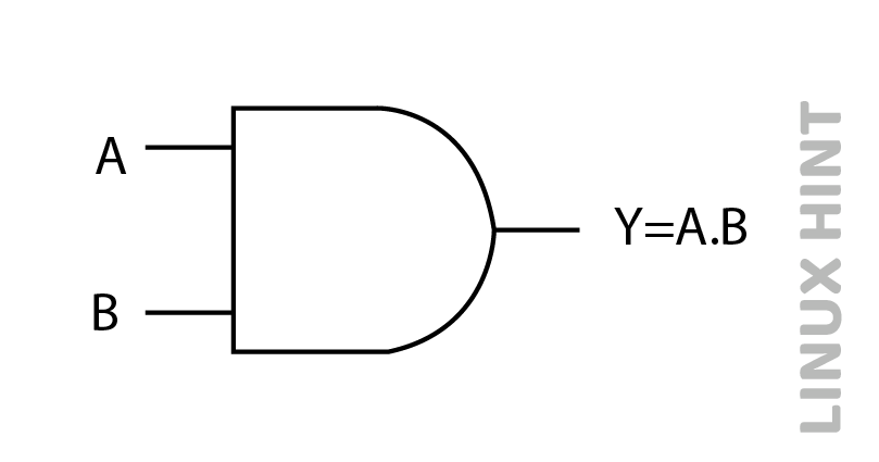
This indicates that when all inputs are ‘1’ the output of an AND gate will be 1.
OR GATE
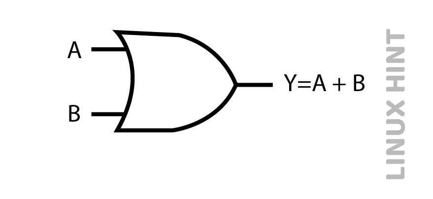
A digital circuit known as an OR gate accepts two or more inputs and outputs the logical OR of all those inputs. The ‘+’ sign stands for this logical OR operation.
The truth table showing inputs and output for an OR gate is provided as under:
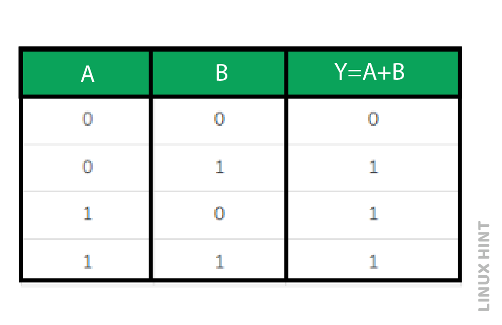
Here, the two input OR gate’s inputs are A and B, and its output is Y. Only the output, Y, is ‘0’ if both inputs are ‘0’. Y returns true for the remainder input combinations. The OR gate’s symbol is shown below. It has one output, Y, and two inputs, A and B.
This indicates that when at least one of the inputs is “1,” the output of an OR gate will be “1”.
NOT gate
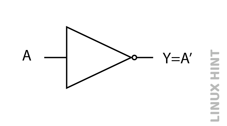
A digital circuit with one input and output is called a NOT gate. The NOT gate’s output is the logical inversion of its input. The NOT gate is called an inverter gate because of its inversion operation. The truth table showing inputs and output of the NOT gate is provided as under:
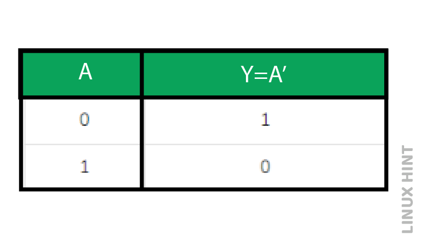
Here, the NOT gate’s input and output are A and Y, respectively. The output, Y shall be true if the input, A, is false. In a similar manner, if input A is true, then output Y is false. The NOT gate, which has one input (A) and one output (Y), is represented by the symbol in the below diagram.
Universal gates
The terms ‘universal gates’ refer to NAND and NOR gates. NAND gates are used to build any Boolean function that takes a sum of products form. Similar to this, we may use NOR gates alone to build any Boolean function that has a product of sums form.
NAND Gate
A digital circuit known as a NAND gate creates an output that is the inversion of the logical AND of all inputs. The truth table showing inputs and output for a NAND gate is provided as under:
Here, the two input NAND gate’s inputs are A and B, and its output is Y. The output, Y, is ‘0’ when both inputs are ‘1’. The output, Y, is ‘1’ if any inputs is zero. The NAND gate symbol is provided as under:
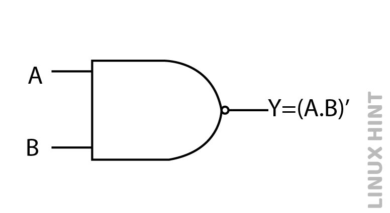
It has one output, Y, and two inputs, A and B. The action of a NAND gate is identical to that of an AND gate with an inverter.
NOR Gate
A digital circuit known as a NOR gate generates an output that is the inversion of the logical OR of all of its inputs with two or more inputs. The truth table showing inputs and output of NOR gate is provided as under:
Here, the inputs are A and B, and the output is Y. The output, Y, is ‘1’ if both inputs are ‘0’. Y is ‘0’ when any of the inputs is ‘1’. The NOR gate, which has two inputs (A, B) and one output (Y), is represented by the symbol in the below diagram.
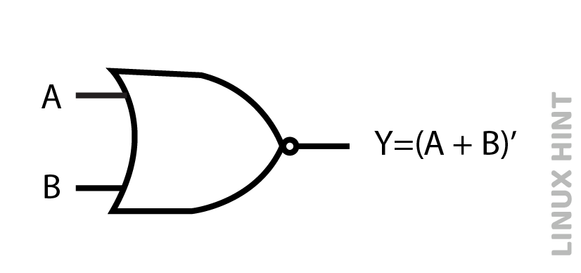
The functioning of an OR gate followed by an inverter relates to NOR gate.
Special Gates
The terms “special gates” refer to Ex-OR and Ex-NOR gates. These are discussed below.
Ex-OR gate
Exclusive-OR gate is the complete name for the Ex-OR gate. When only one of two digital inputs is a 1, the Ex-OR gate output is a 1. However, when both digital inputs are the same ones, it provides zero output. The truth table showing inputs and output for an Ex-OR gate is provided as under:
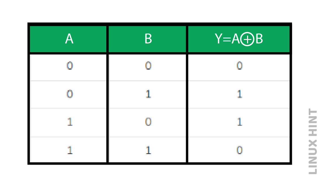
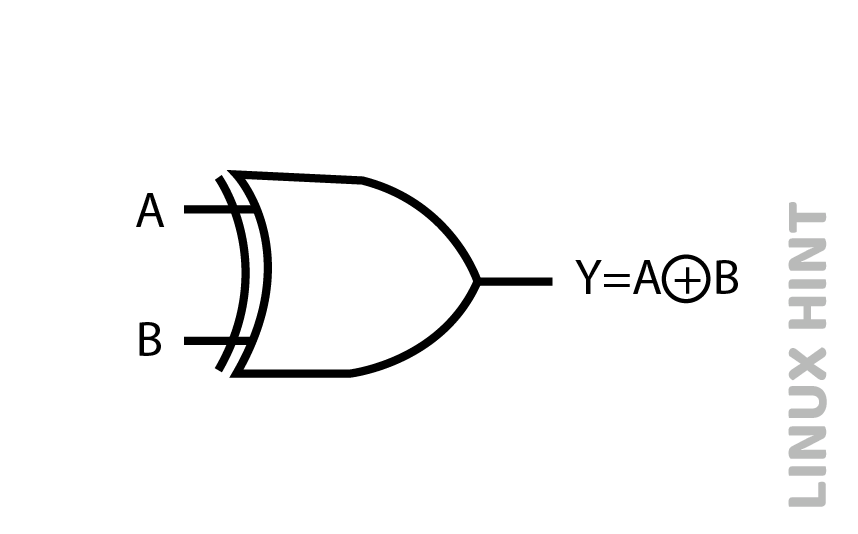
Here, the two input Ex-OR gate’s inputs are A and B and Y as output. For the first of three input combinations, the truth table of the Ex-OR gate is similar to that of the OR gate. The fourth row is the only exception that has changed from OR logic. The Ex-OR gate, which has one output, Y, and two inputs, A, B, is represented by the symbol in the below figure:
When there are an odd number of ones at the inputs, the Ex-OR gate produces the value “1”. As a result, the Ex-OR gate’s output is sometimes referred to as an odd function.
EX NOR gate
Exclusive-NOR gate is the full name for Ex-NOR gate. When both of two digital inputs are the same, the Ex-NOR gate’s output is 1. When two of the inputs are different to each other, its output is zero. The truth table showing inputs and output for Ex-NOR gate is provided as under:
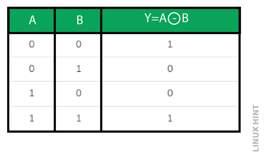
Here, the inputs are A and B, and the output is Y. For the first three input combinations, the truth table of the Ex-NOR gate is quite similar to that of the NOR gate. The fourth row is the only area that has changed. This indicates that when both of the digital inputs are 1, the output is returned as 1 rather than 0. The Ex-NOR gate, which has one output, Y, and two inputs, A, B, is represented by the symbol in the accompanying image.
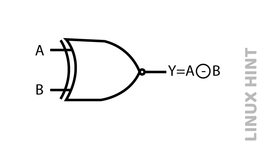
When an even number of ones are present at the inputs, the Ex-NOR gate produces the value “1”. As a result, the Ex-NOR gate’s output is sometimes referred to as an even function.
Basic Building Circuits for Logic Gates
Each digital logic gate can be created using three elements: resistors, diodes and transistors. A simple combination of two diodes with resistor provides the electrical circuit for the AND logic gate. This circuit can be modified to other digital gates by addition of a combination of transistors and resistors.
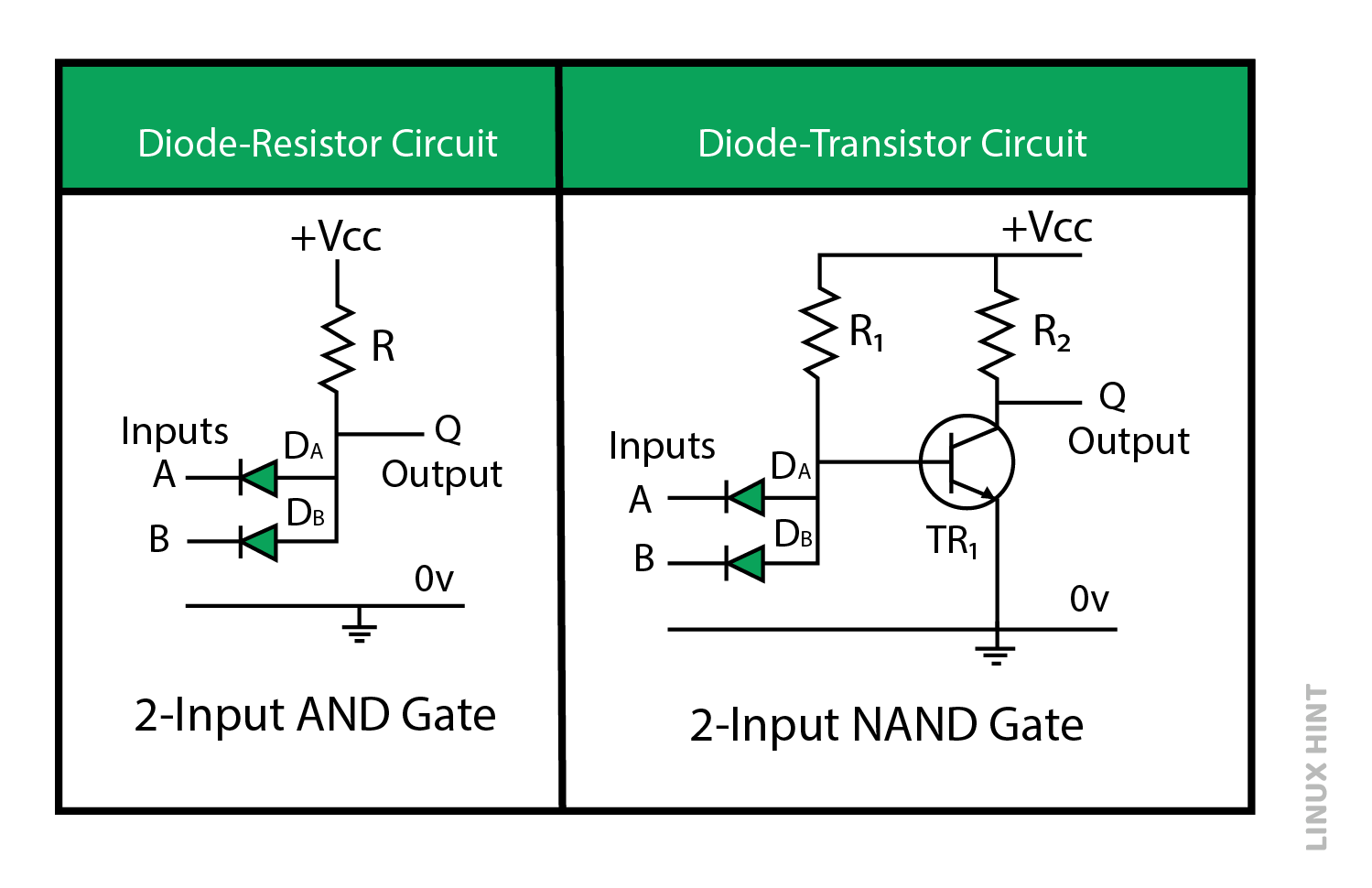
In the above circuit, an NPN transistor has been added with resistor R2 to convert the AND gate circuit into NAND gate. The other logic circuits can be created with different arrangements of the above circuit elements. The commercially available logic ICs do not make use of such discrete elements in circuits due to power loss and gate delays limitations. These ICs can include from 10 to thousands of individual transistors and fewer logic gates to thousands of logic gates within a single package.
Conclusion
Logical gates are a part of every digital electronic circuit. They can perform the basic arithmetic operations on digital inputs to complex operations of input data comparators, adders, subtractors as well as integrators.
Source: linuxhint.com