Connecting ESP32 & ESP8266 to Arduino Cloud IoT
Connecting ESP32 or ESP8266 development boards with the Arduino Cloud IoT helps to increase productivity and control appliances using the internet from anywhere around the world. This step-by-step guide will take you through the process of setting up your board with the Arduino Cloud IoT, testing it out by sending random values to the cloud, and setting up a switch to enable the built-in LED on the board.
Main content of this article includes:
- Setting up the Arduino Cloud IoT
- Step 1: Setting up the device
- Step 2: Creating a Thing
- Step 3: Adding credentials
- Step 4: Programming the board
- Step 5: Creating a dashboard
- Troubleshooting
- Conclusion
Goals
The objective of this guide is:
- Transmit data from the development board to the Cloud.
- Control the ON/OFF state of an LED through Arduino IoT Cloud.
Hardware & Software Needed
To execute this project, the following hardware and software are required:
- An ESP32/ESP8266 development board.
- The Arduino Cloud IoT platform.
In addition, the following components are necessary for the circuit:
- An LED
- A 220-ohm resistor
- A breadboard
- Jumper wires
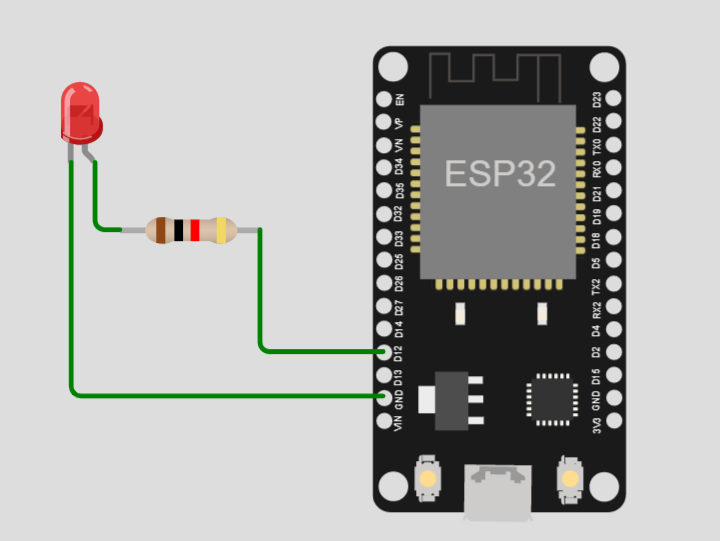
Circuit
Here we are going to connect ESP32 with an LED at pin D12.
Note: If you want to control the inbuilt LED then this circuit is not needed. The on-board LED of ESP32 is at pin D2.
Setting up the Arduino Cloud IoT
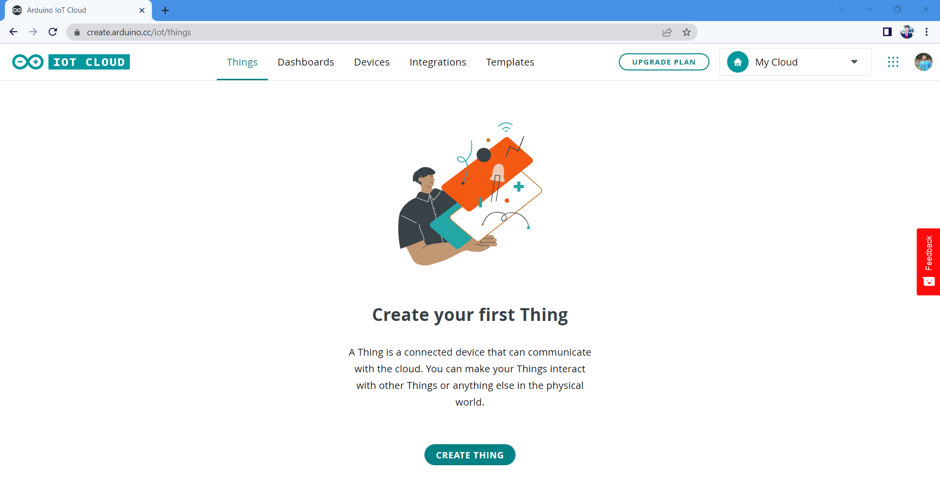
Before we begin, we must set up the Arduino Cloud IoT. Open the IoT portal and sign in or create a new account.
The first step is to set up your device with the Arduino Cloud IoT. Here’s how:
Step 1: Setting up the device
After creating the Arduino IoT Cloud, the next step is to link the device. Follow given steps to link your ESP32/ESP8266 board with Arduino Cloud IoT:
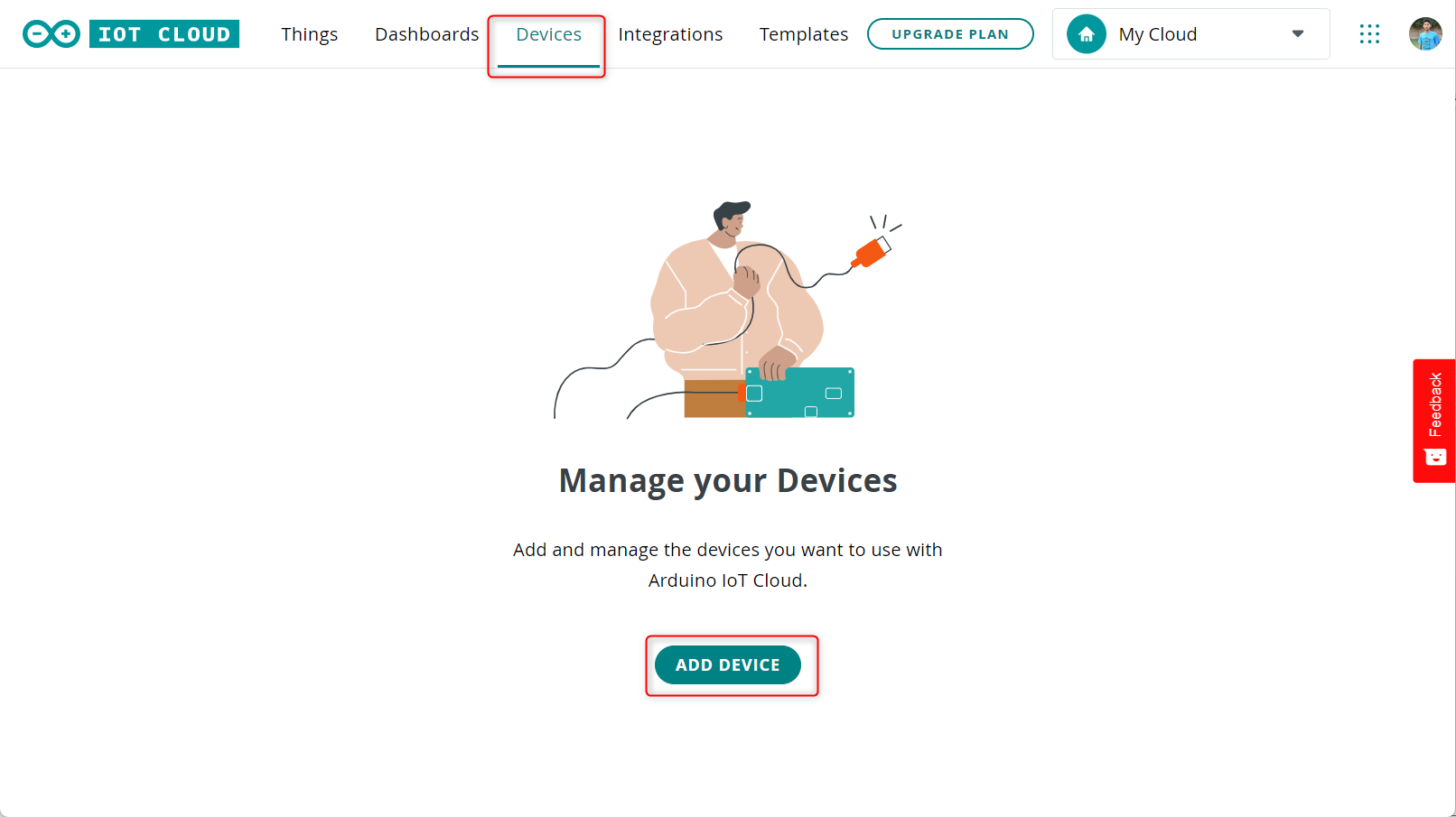
1. The first step is to click the Devices tab. Then, click Add device.
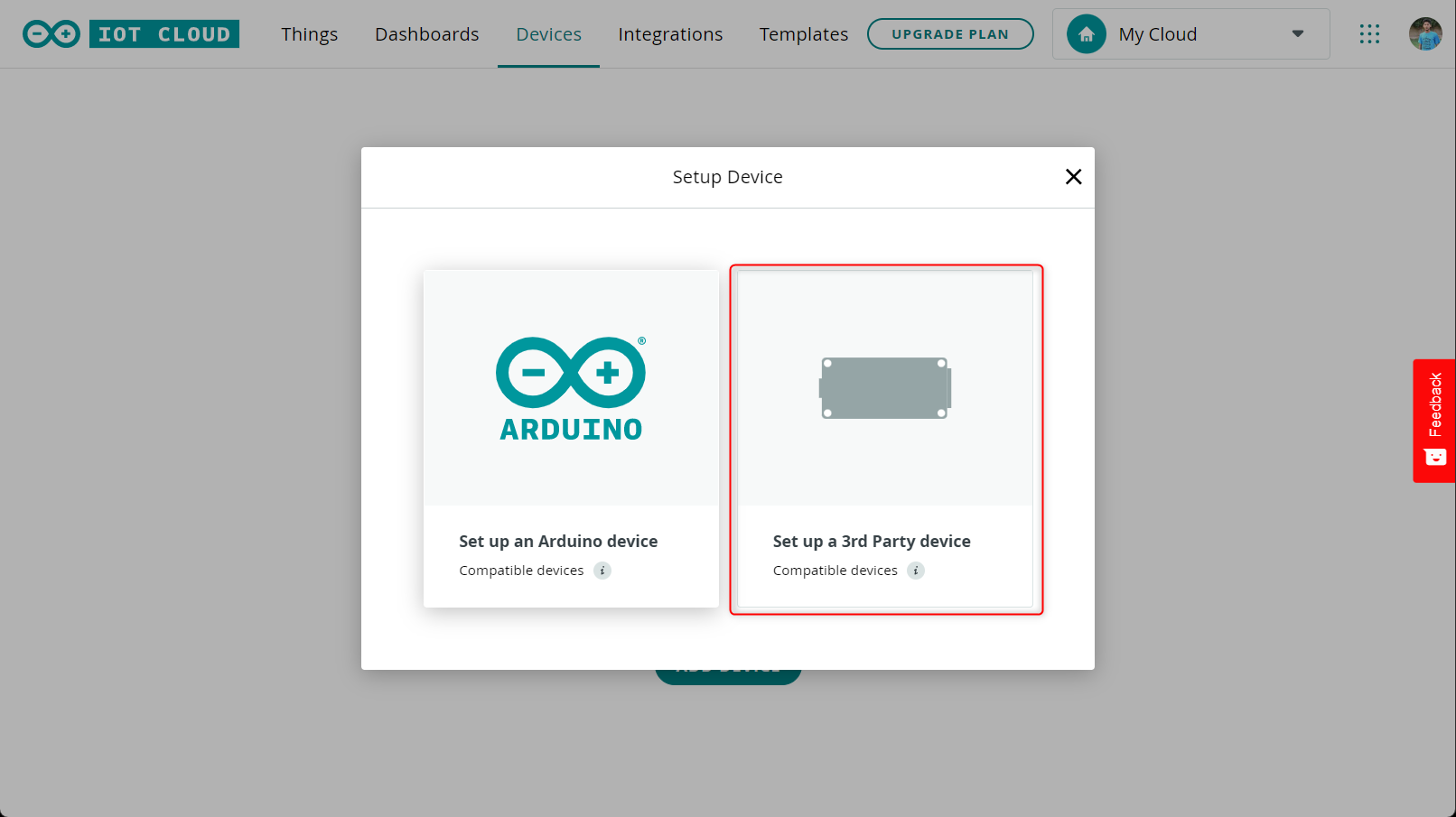
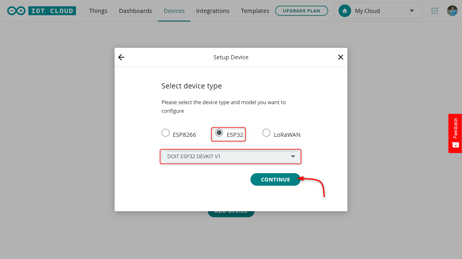
2. As we are not adding any Arduino board so select the third part board option.
3. Now select the board which you are using after selecting the board next select the board type from the drop-down menu. After that click continue.
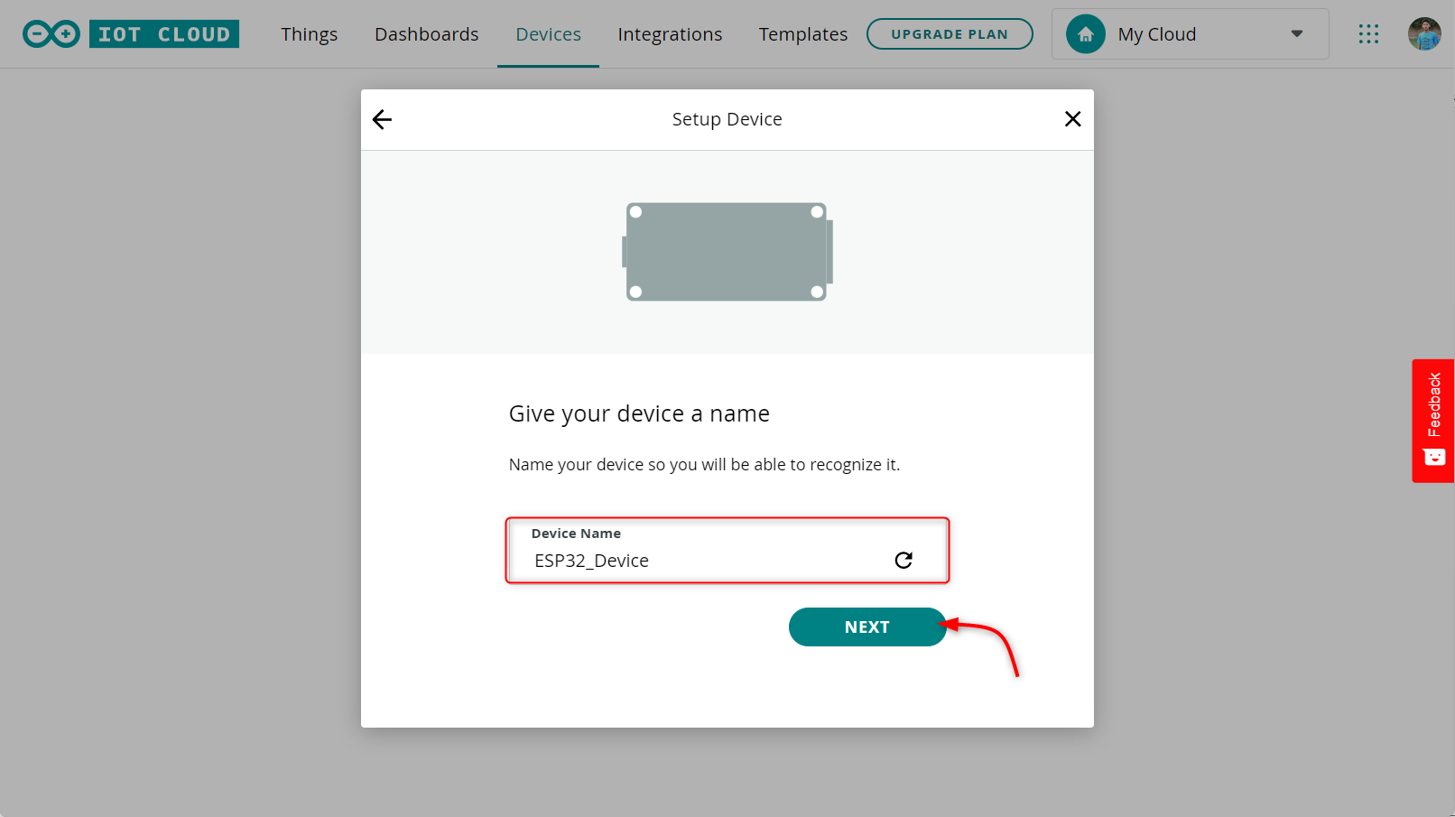
4. Type a device name to get it recognizable by nearby devices.
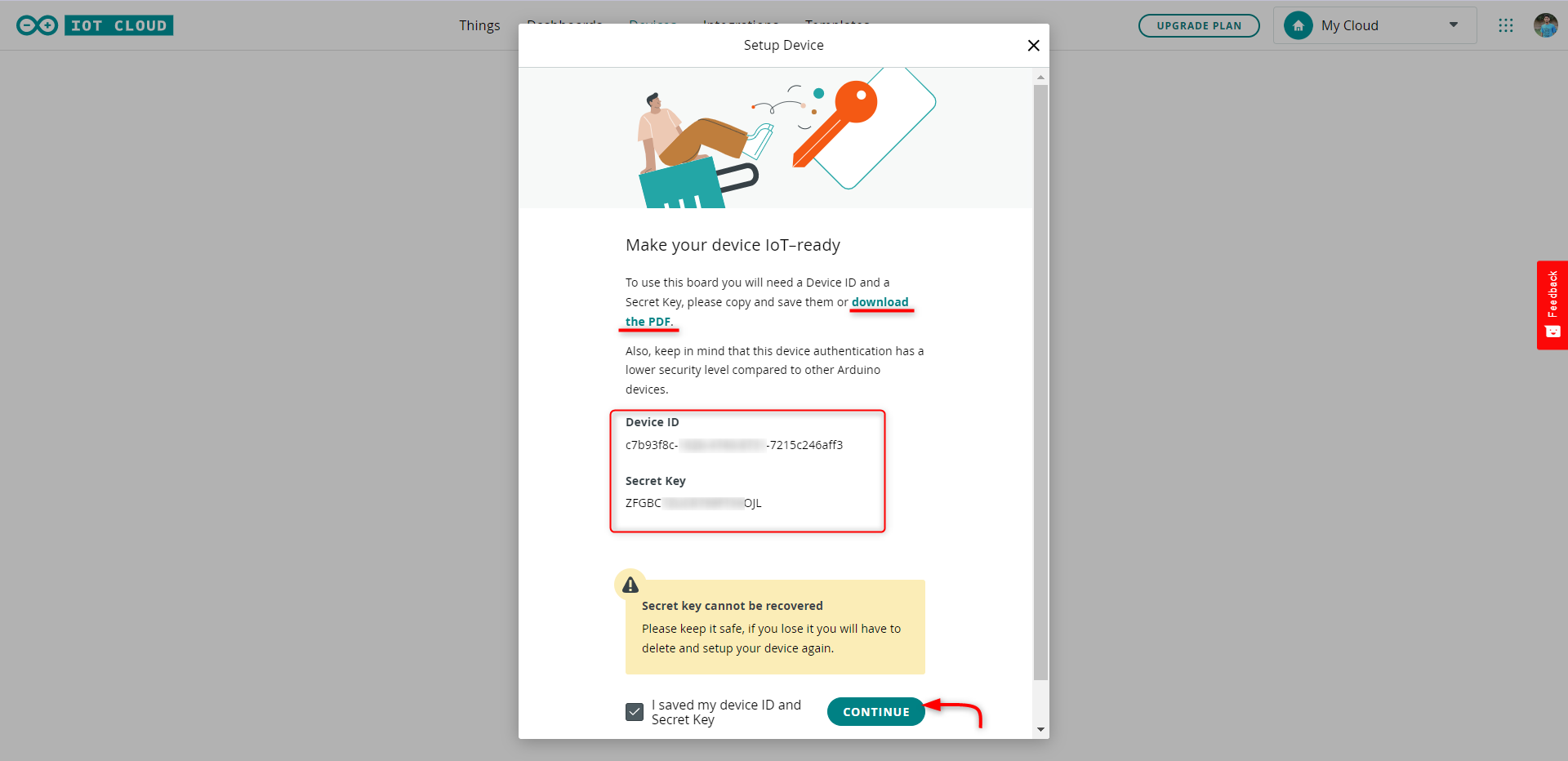
5. After that a unique Device ID and Security Key will be given to you. Save this key or download the PDF file which contains this information.
Note: This key is not recoverable so try not to lose it otherwise you have to add the device again.
After saving the details, tick the box and click the continue button.
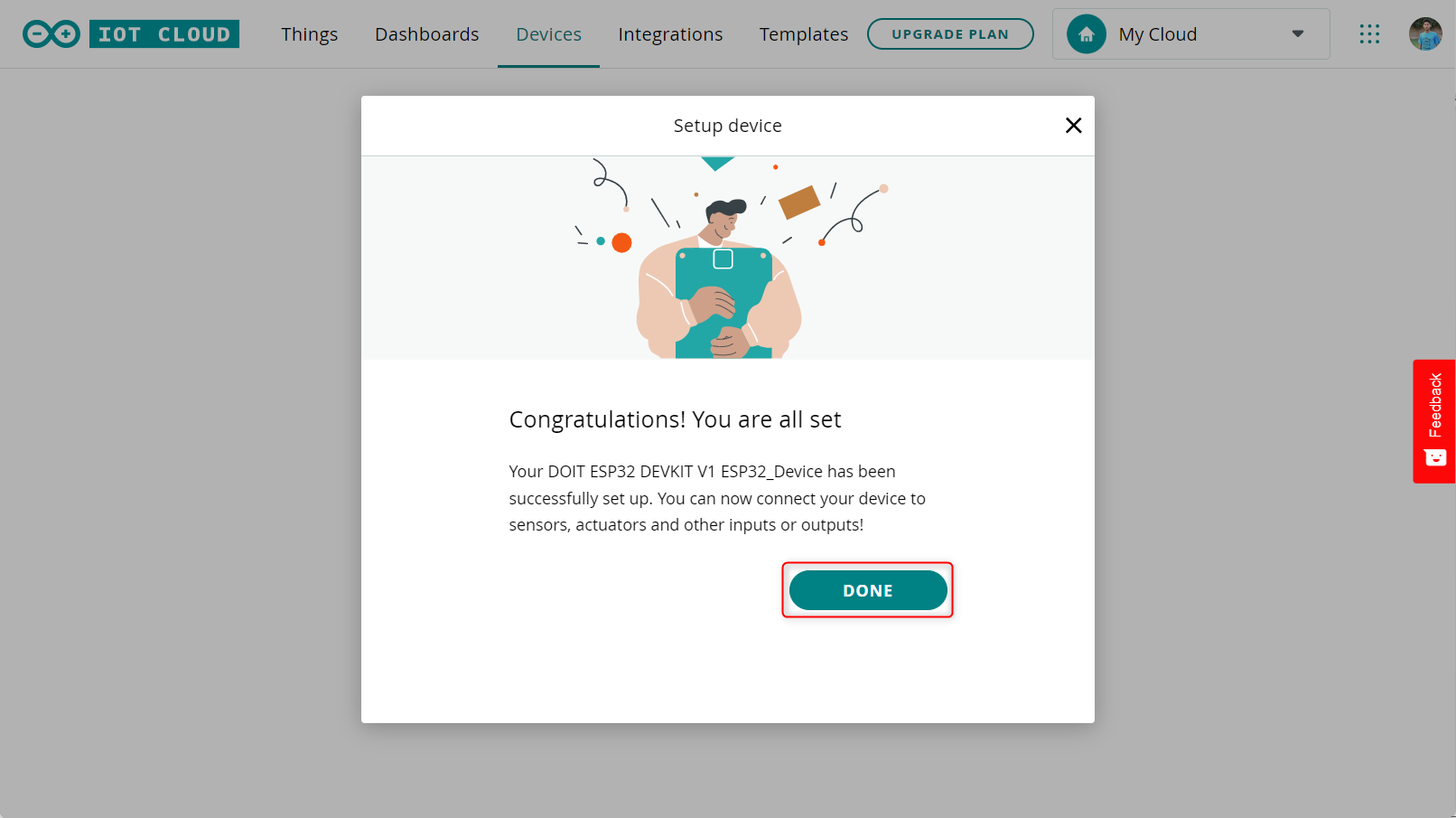
We have successfully added our ESP32 board to Arduino IoT Cloud. Click Done.
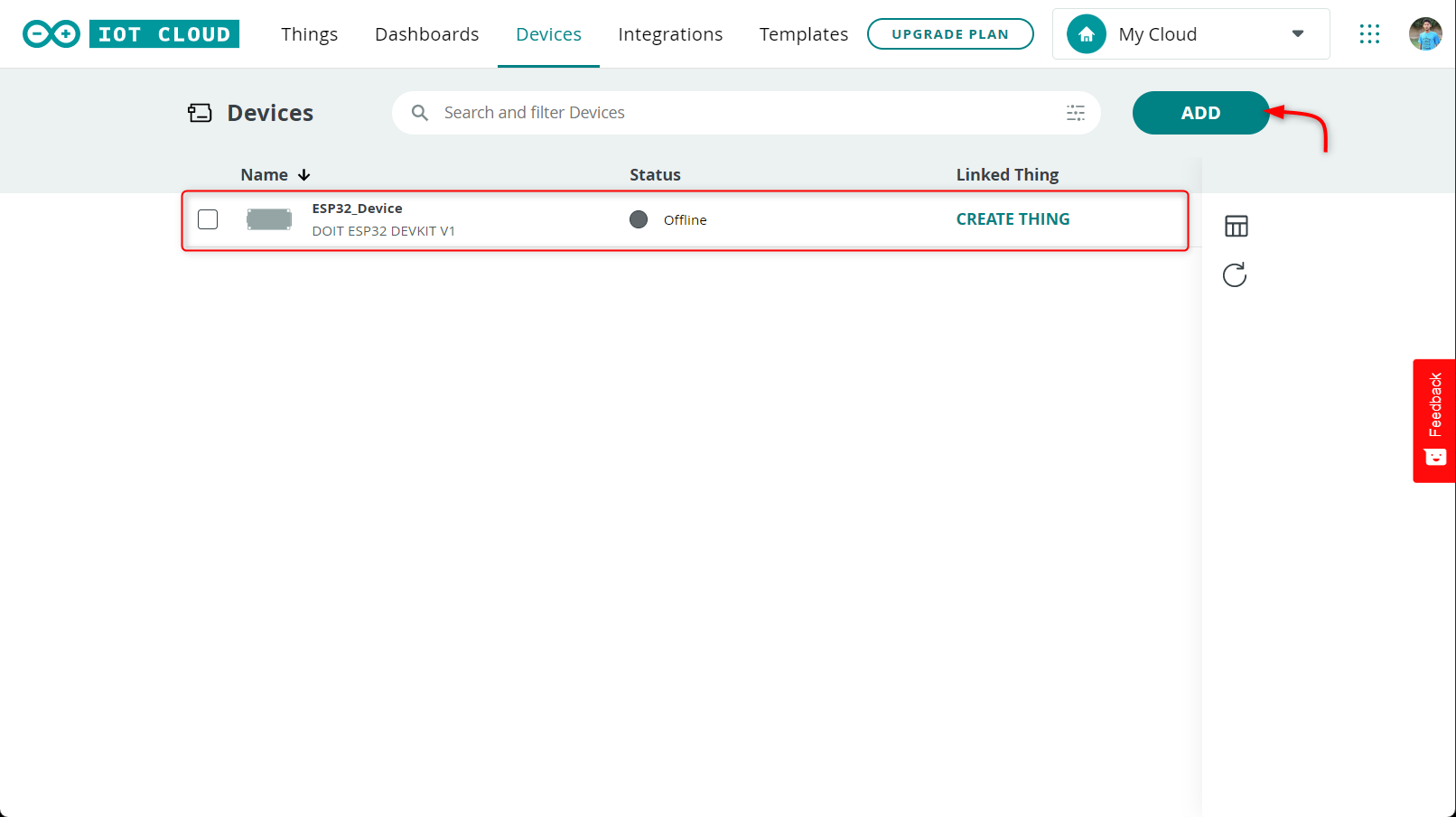
Similarly, we can also add multiple devices by using the Add button on top right. All our devices will be listed here as shown in image:
Step 2: Creating a Thing
Now we have successfully added our device. Next step is to create a thing for the ESP32 board. Follow the given steps:
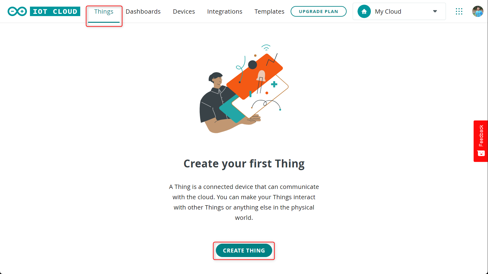
1. Open the Things tab on the cloud platform and click Create Thing.
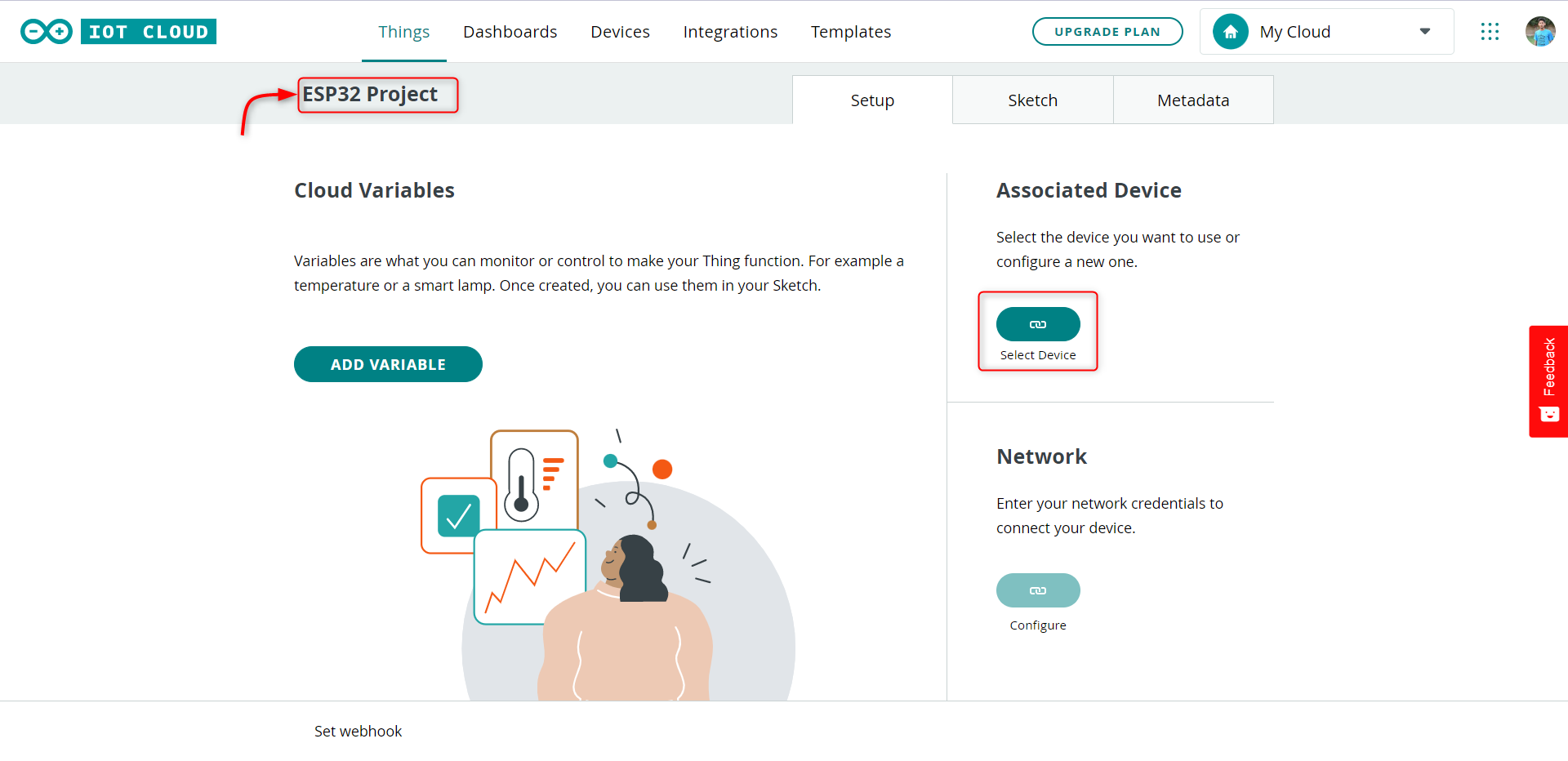
2. Now we can also rename our device if we want. Next under Associated Device select the device for which you want to create a Thing.
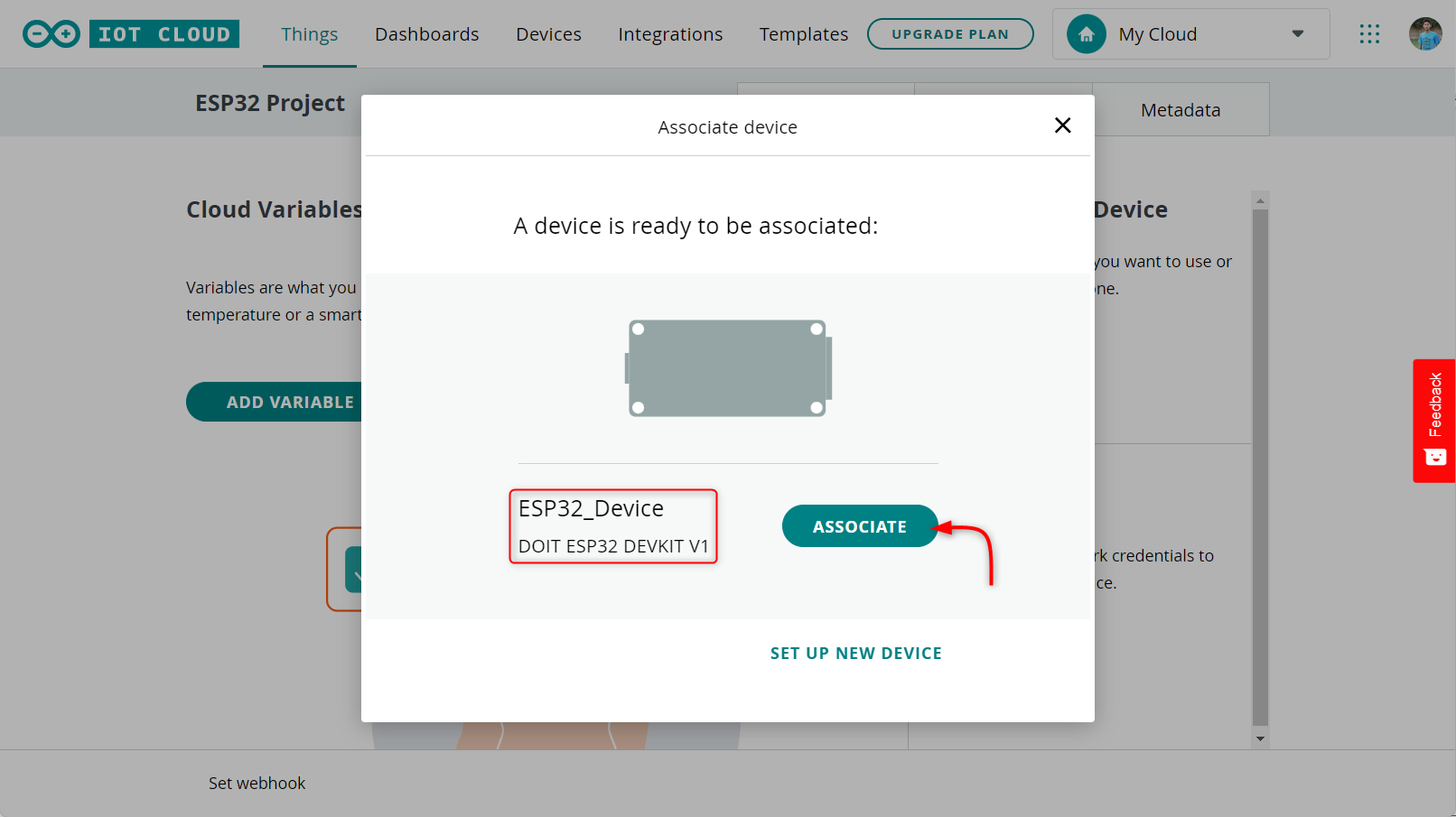
3. Select the device and click Associate. You can also set up a new device from here.
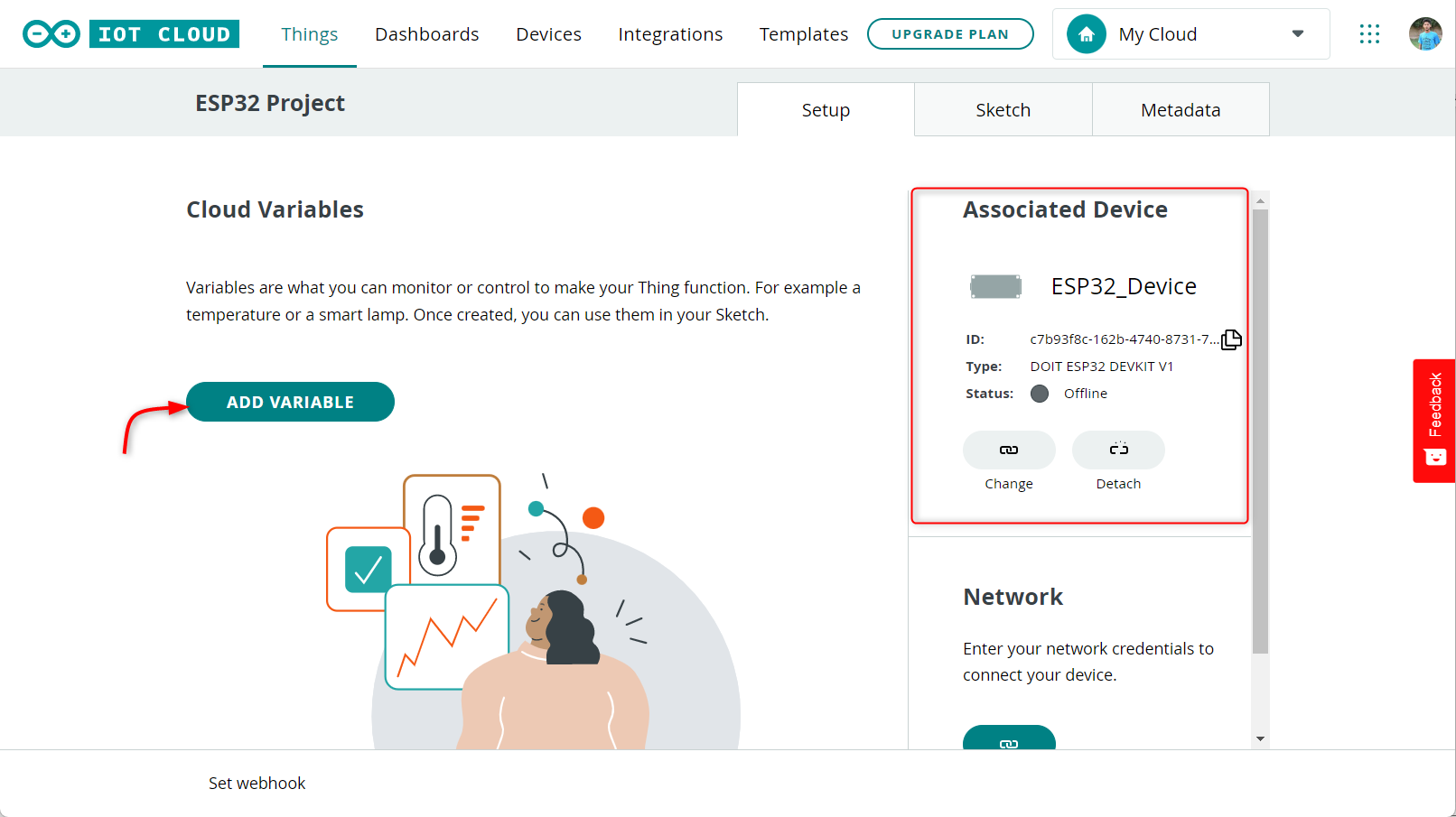
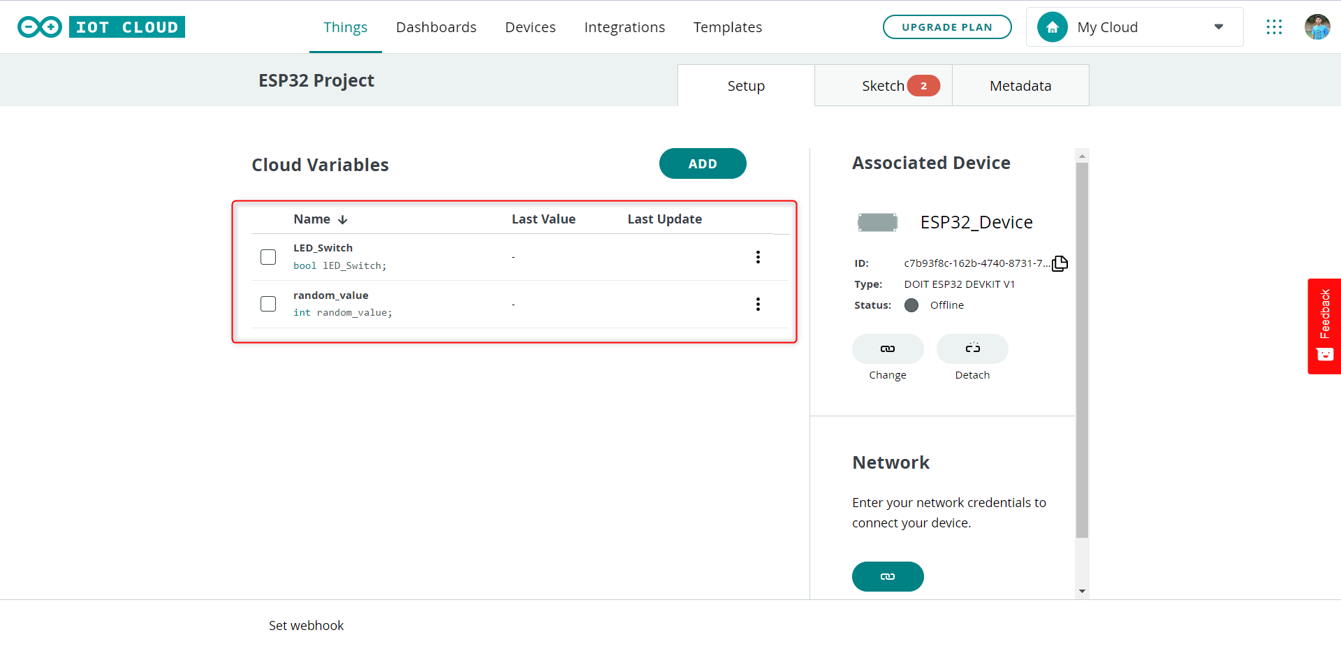
4. After establishing a connection between the device and the cloud, the next step is to create two variables namely, random_value and led_switch. To do this, click on the Add variable button which will open a new window where you must provide the necessary information for the variables.
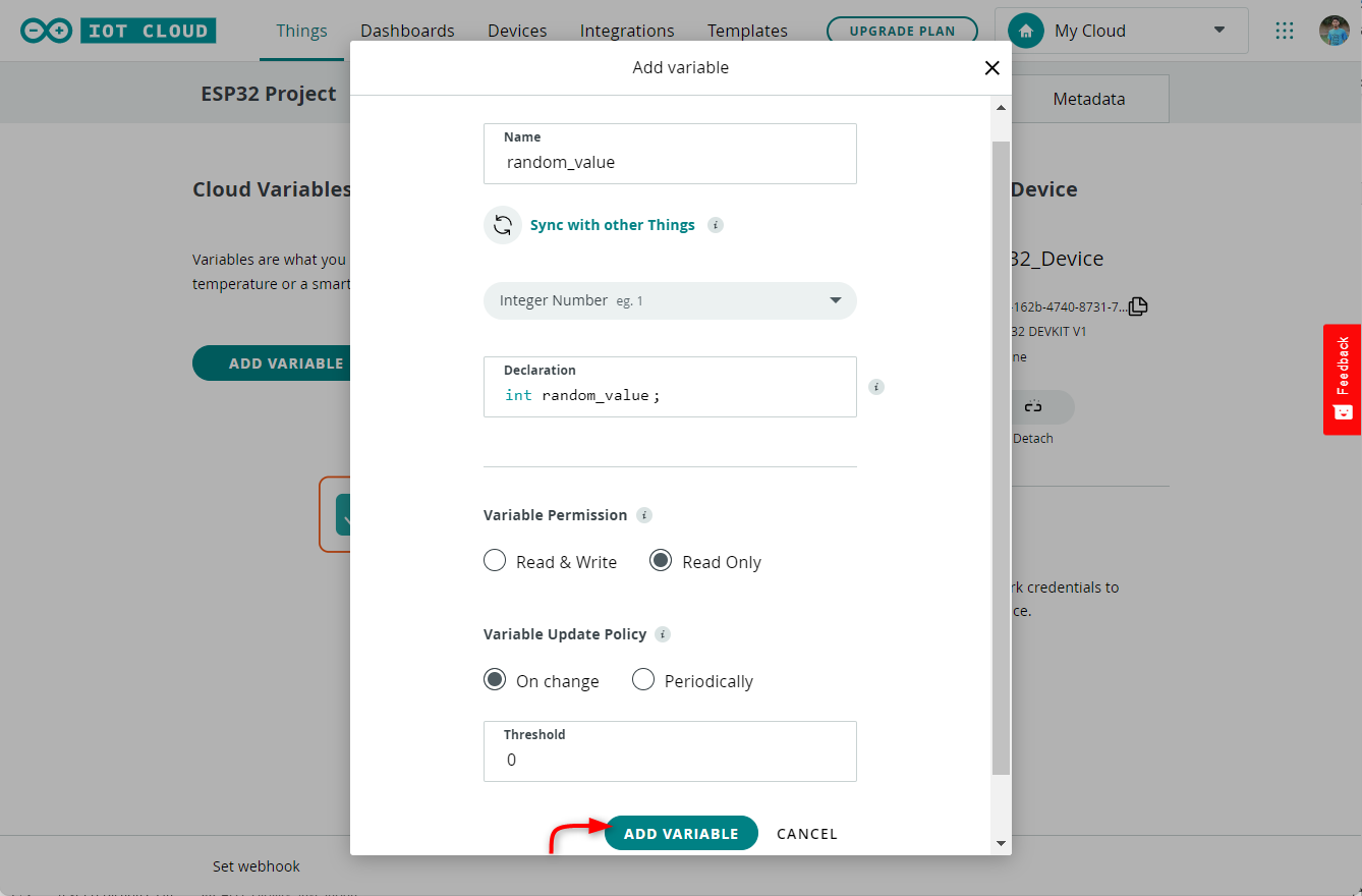
5. Now, we can start creating the “random_value” variable. To do this, we should select the int data type, set the permission as read-only, and the update policy as on change. After setting these parameters, we can click on the “Add variable” button to complete the process.
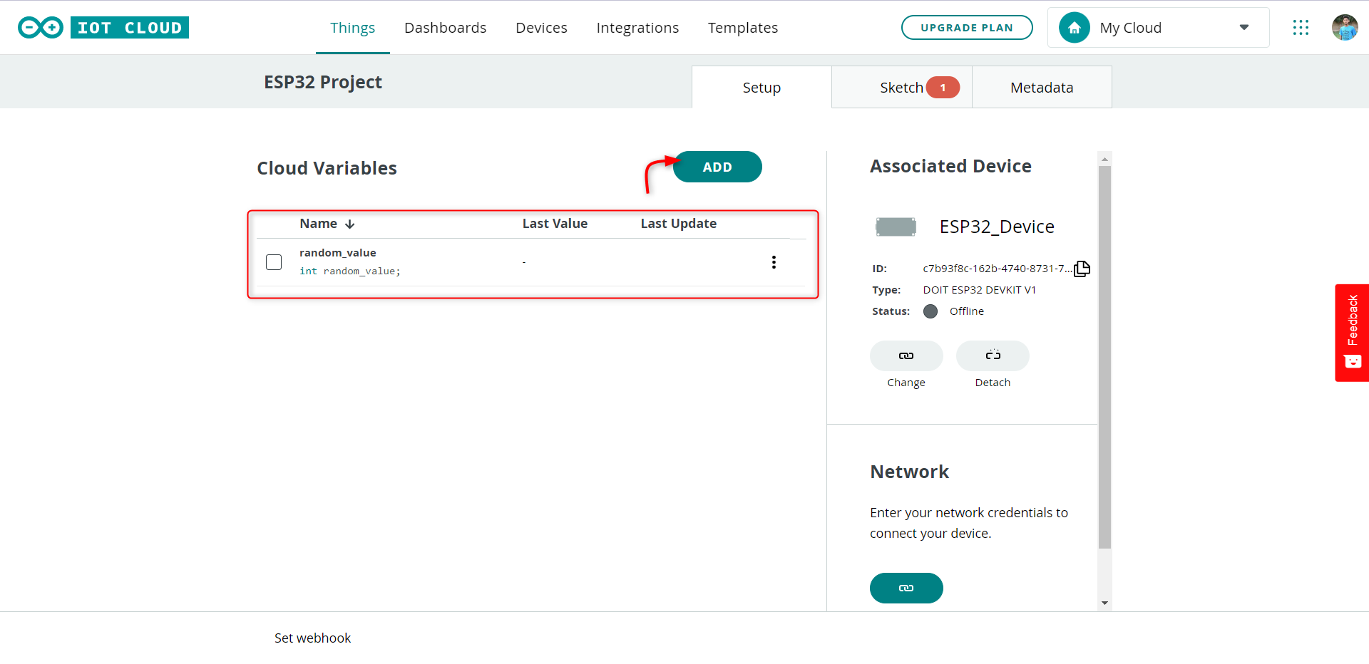
6. After adding the random variable, we can see it listed in the cloud variables section.
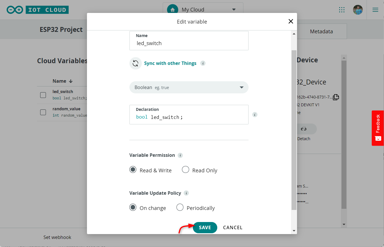
7. Next, we’ll add the led_switch variable. This variable will have a data type of boolean, with read and write permissions, and an update policy of on change. To add this variable, click on the Add variable button and fill in the required information.
Once done click save.
8. Similarly, we can also add other variables for different tasks. Currently both variables are listed here.
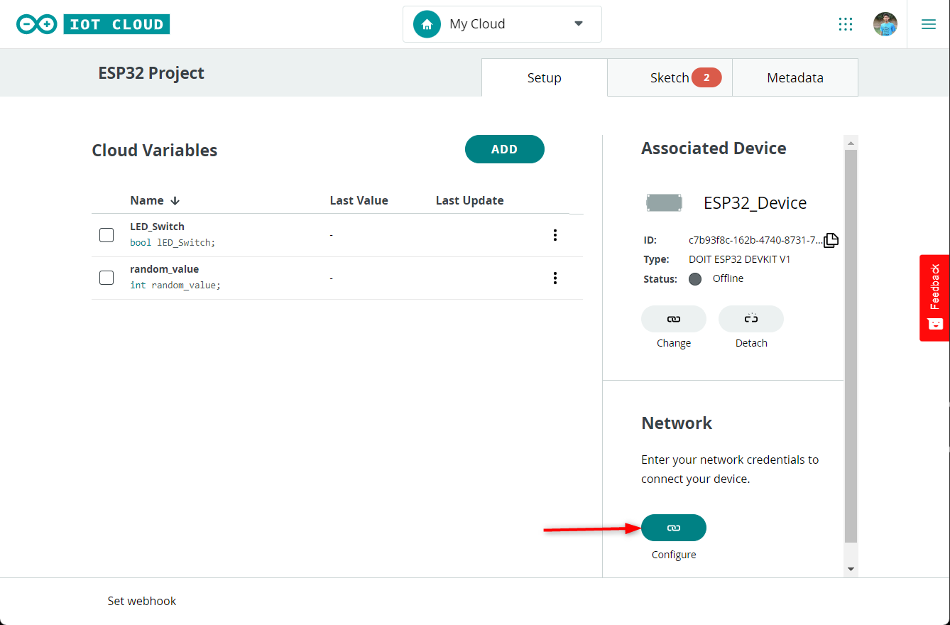
Step 3: Adding credentials
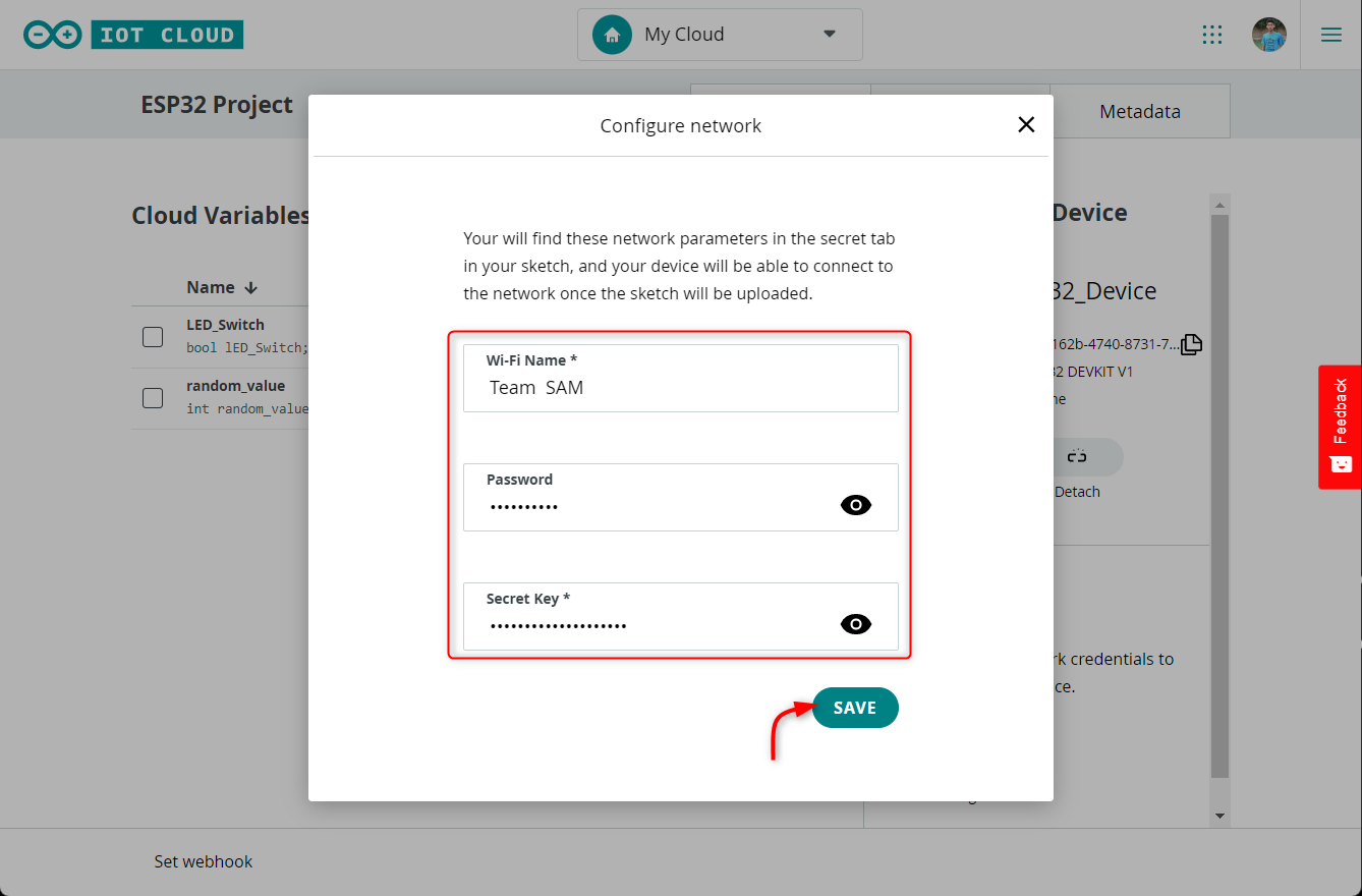
Once the board and variable have been added, the next step is to establish a connection between the ESP32 board and an online network. This can be done by clicking on the button located in the Network Section and entering the necessary credentials for the network, as well as the secret key that was generated during device configuration.
Now enter all network details including the Secret key. Click Save to finish.
Step 4: Programming the board
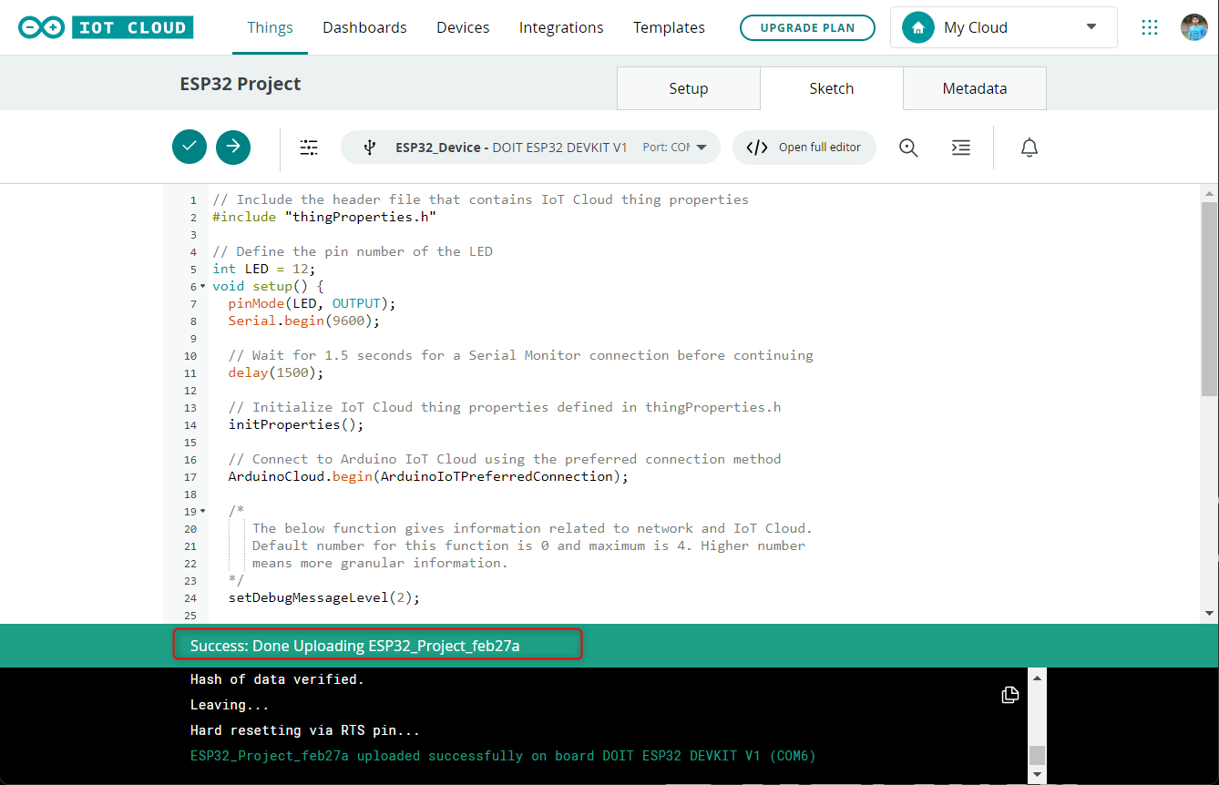
After saving all the information the last step on the list is write and upload the Arduino code to test all the processes.
Navigate to the Sketch tab and upload the code given below.
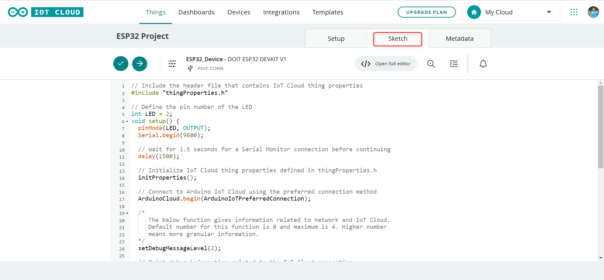
It is worth noting that the LED in this tutorial is connected to pin 13, however, you can easily modify it to use a different GPIO by updating the LED variable accordingly.
Complete Sketch
Following is the complete code to upload in the ESP32 board.
#include "thingProperties.h"
// Define the pin number of the LED
int LED = 12;
void setup() {
pinMode(LED, OUTPUT);
Serial.begin(9600);
// Wait for 1.5 seconds for a Serial Monitor connection before continuing
delay(1500);
// Initialize IoT Cloud thing properties defined in thingProperties.h
initProperties();
// Connect to Arduino IoT Cloud using the preferred connection method
ArduinoCloud.begin(ArduinoIoTPreferredConnection);
/*
The below function gives information related to network and IoT Cloud.
Default number for this function is 0 and maximum is 4. Higher number
means more granular information.
*/
setDebugMessageLevel(2);
// Print debug information related to the IoT Cloud connection
ArduinoCloud.printDebugInfo();
}
// Loop function runs continuously after setup() finishes
void loop() {
// Update the connection status and properties of the device with IoT Cloud
ArduinoCloud.update();
// Generate a random value between 0 and 500
random_value = random(0, 500);
// Wait for 500 milliseconds before generating the next random value
delay(500);
}
// This function is called whenever there is a change in the state of the led_switch property in IoT Cloud
void onLedSwitchChange() {
if(led_switch){
digitalWrite(LED, HIGH); // Turn on the LED if led_switch is true
}
else{
digitalWrite(LED, LOW); // Turn off the LED if led_switch is false
}
}
After uploading the code, a message indicating success should appear in the console located at the bottom of the editor.
Step 5: Creating a dashboard
Now ESP32 board is ready to be controlled using the Arduino IoT cloud the only step left is to create an interactive dashboard for LED control. Follow steps to create a dashboard for the above Arduino code:
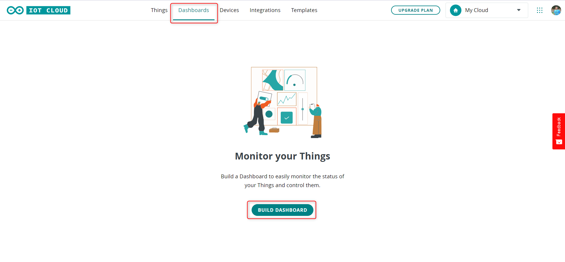
1. Open the Dashboards tab and select Build dashboard.
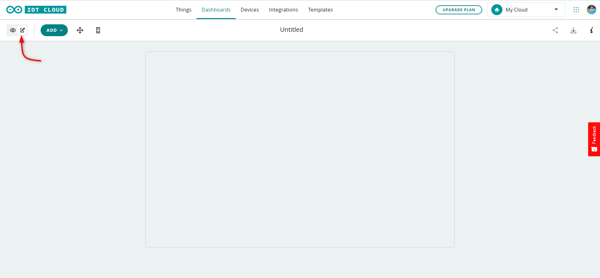
2. To make changes select the pencil icon situated at the left corner of the screen.
3. Select Things and look for the Thing we created earlier. After finding the Thing click Add widgets.
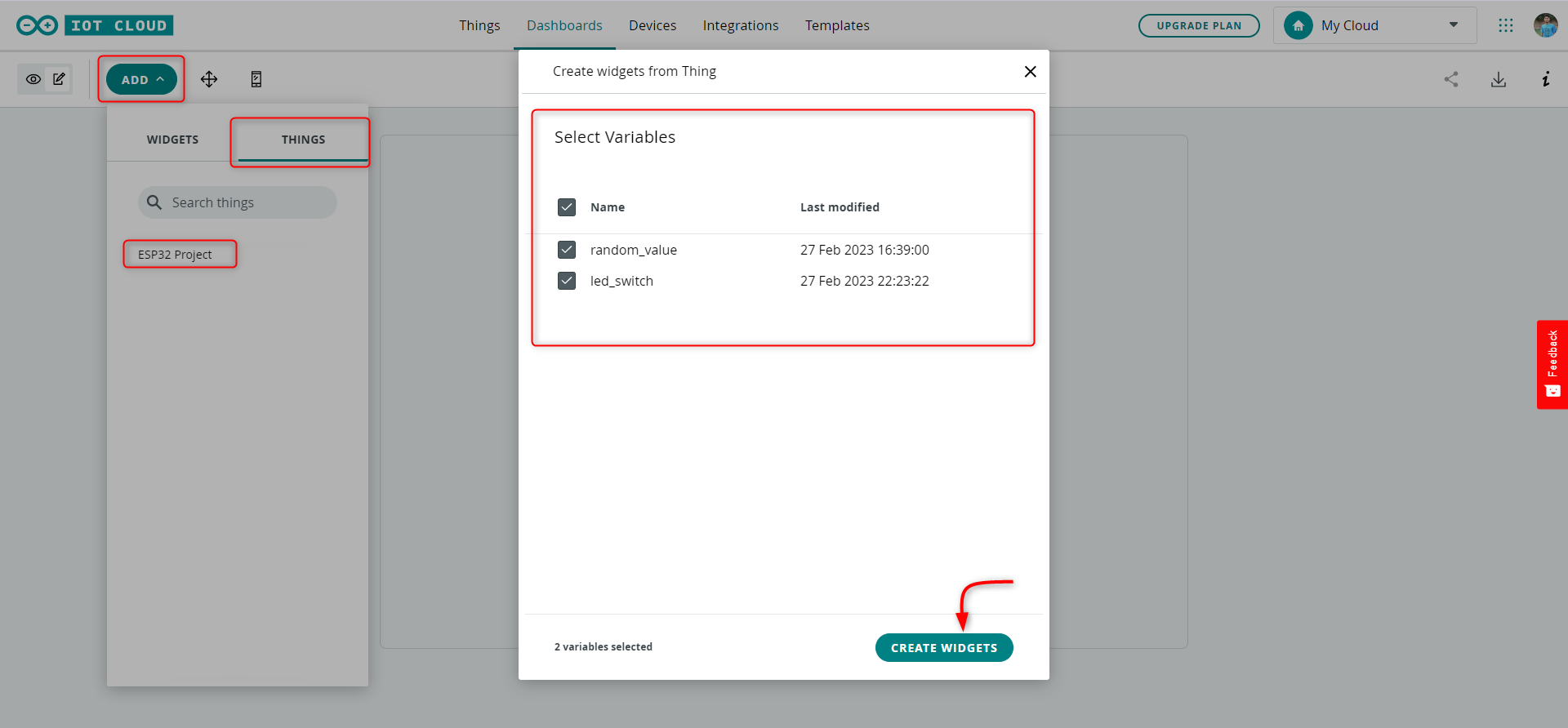
We have successfully linked two widgets to your board:
- random_value: This widget updates in real-time whenever the random_value changes on the board.
- led_switch: You can use this switch to turn ON/OFF the LED connected to the board through pin 12.
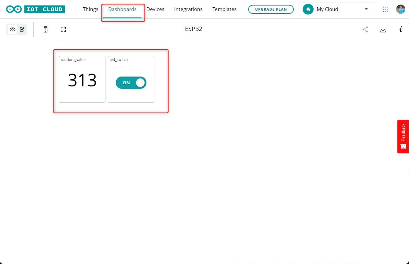
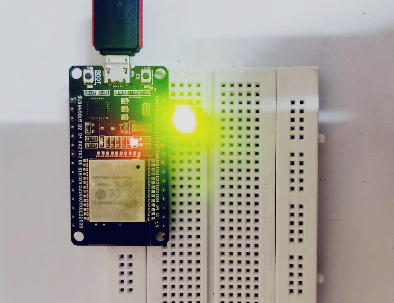
The LED at pin D12 can be controlled using the toggle button we created inside our Arduino IoT cloud dashboard.
Troubleshooting
If you encounter difficulties in completing this tutorial, ensure that the following are accurate:
- The correct secret key has been entered in the credentials window.
- The correct network name and password have been entered in the credentials window.
- Ensure that the appropriate device has been selected from your registered devices in the cloud. If you have multiple devices, double-check that you have selected the right board.
- Make sure the Arduino Create Agent is installed in your system.
Note: The Arduino Cloud IoT is in the beginning and experimental stage for ESP32 support and working.
Conclusion
This tutorial covered the fundamental steps involved in establishing communication between an ESP32 / ESP8266 microcontroller and the Arduino Cloud IoT. The demonstration involved sending random data from the board to the cloud and creating a switch that remotely controls an LED through the cloud.
Source: linuxhint.com