Arduino Uno Pinout Guide
Arduino platform provides a variety of the microcontroller boards also known as Arduino boards that come with different specifications. Before using any Arduino board, one must know the specification of the boards and most importantly the pinout of the boards. So, we have explained the pinouts of the Arduino Uno board and the use of each pin in detail.
Arduino Uno
The most used board among the Arduino family is the Arduino Uno as it is easy to use and suitable for beginner and medium level electronic projects. This board is equipped with an ATMEGA328P microcontroller which belongs to the ATMEL family.
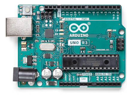
This board can operate on the voltage of 5-volts and has flash memory of 32 kilobytes. Whereas the static RAM of the controller is 2 kilobytes and the EEPROM has memory of 1 kilobyte. The clock speed of the ATMEGA328P is 16 Hz. Below is the image of the Arduino Uno board:
Arduino Uno Pinout
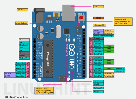
The Arduino Uno has a total of 31 pins (1 NC) among which 14 pins are digital pins that can be used for digital inputs and output. 6 of them are the analog pins that can be used for analog inputs and outputs and there are 10 pins that can be used to supply power to the connected devices.
| Pin Category | Representation | Description |
| Power Pins of Arduino Uno | 5V, RESET,
3.3V, GND (3), Vin, AREF, IOREF |
Pins used to deliver power to the device connected with Arduino |
| Digital Pins of Arduino Uno | 0 to 13 | Pins used for digital input and outputs of Arduino |
| PWM Pins of Arduino Uno
(Digital pins) |
11,10, 9, 6, 5, 3 | Pins used to generate the pulsating signal |
| Analog Pins of Arduino Uno | A0 to A5 (A5 for SCL and A4 for SDA) | Pins used for analog inputs and outputs of Arduino |
| Miscellaneous Pins of Arduino Uno | Additional pins for SCL and SDA (One not connected pin [NC])
|
SCL is the clock pin and the SDA is the data pin for I2C and TWI communication devices |
| 12 header Pins of Arduino Uno | ICSP | Pins used to reprogram the Arduino |
This board also consists of the 12 header pins as well also called In Circuit System Programming (ICSP) pins.They are also used to program the controller We have explained each pin by dividing the pins on different categories based on their usage in the subsequent paragraphs.
Digital Pins of the Arduino Uno
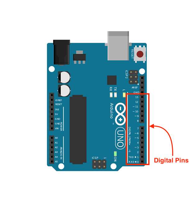
There are a total of 14 digital pins of the Arduino which can be used for connecting the devices that require digital input from the Arduino Uno and give the digital output. For the digital we mean that the information will be in the form of zero and one.
Pin 0 and 1 in the digital pins are the communication pins of the Arduino labeled as TX and RX. Through these pins the Arduino communicates with the different communication devices and is also used when uploading the code to the Arduino board.
There is a built-in LED in the Arduino Uno that is connected to pin 13 but we can use this pin to connect other devices as well.
Below we have attached the image of the Arduino Uno in which the digital pins are highlighted in red color.
Analog Pins of Arduino Uno
The Arduino Uno has 6 analog pins that are mainly used to connect the analog devices (sensors) and have the resolution of 0 to 1023. This means that the values will be in between 0 and 1023 and in terms of voltage the 5 volts will be 1024 that is 2^10.
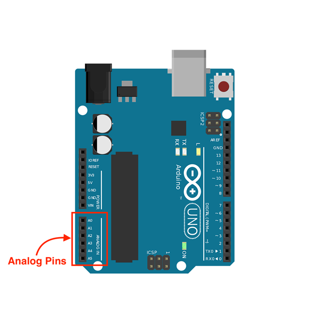
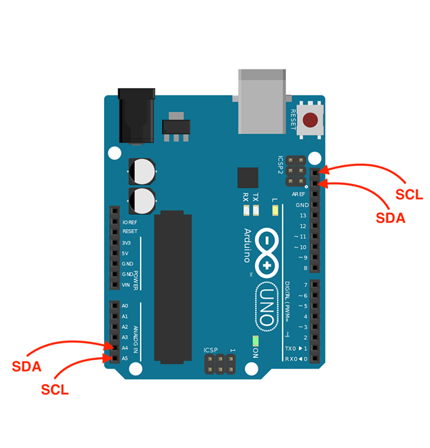
The pins A4 and A5 can be used as the SDA and SCL pins for the devices that used I2C and TWI (Two Wire Interface) communication protocols. The SDA pin is the data line for the connected device and SCL is the clock pin of the connected device. Similarly, there are two other pins next to the AREF pin that can be used for the data line and clock of the I2C devices as well.
The figure attached below shows the analog pins of the Arduino by highlighting it in red.
Power Pins of Arduino Uno
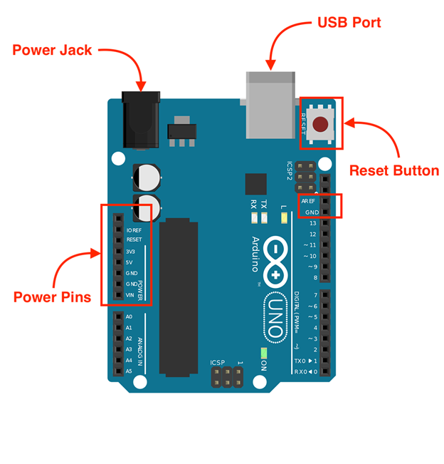
The Arduino Uno has a total of 10 pins that are used for supplying power to the devices connected with Arduino. The maximum voltage the Arduino Uno can supply is 5 volts and minimum voltage of 3.3 volts and there are four ground pins in the board.
Similarly, there are IOREF and AREF pins that are used to provide reference voltage for the devices connected to Arduino Uno. The AREF is the voltage reference for the analog devices whereas the IOREF is the reference voltage to the other digital devices. There is also a reset pin given in the board to RESET the Arduino Uno using an external button. However, there is a dedicated RESET button given on the Arduino Uno board.
To connect the Arduino board with the supply voltage there is one USB port and a jack for power supply is also provided. The USB port can be used for power as well as to upload the code to the Arduino Uno. Whereas the jack provided for the supply is mostly used when the Arduino has to function in standalone mode. The image below shows the power supply pins and the RESET button of the Arduino uno.
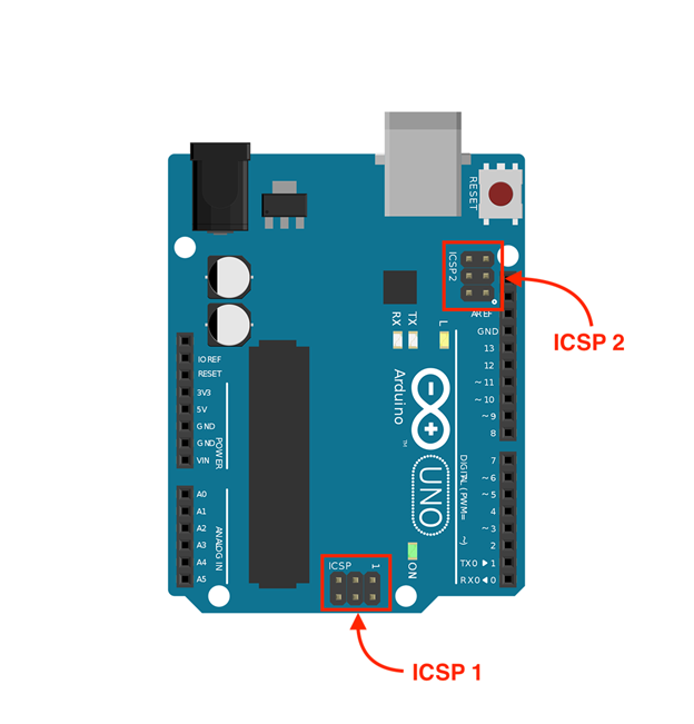
ICSP Header Pins of the Arduino Uno
To update or change the firmware of the Arduino Uno we can use the 12 header pins given on the Arduino Uno board. The in-circuit system programming (ICSP) can be done by connecting Arduino with the device using a programming cord. We have highlighted the ICSP header pins of Arduino Uno in the image given below.
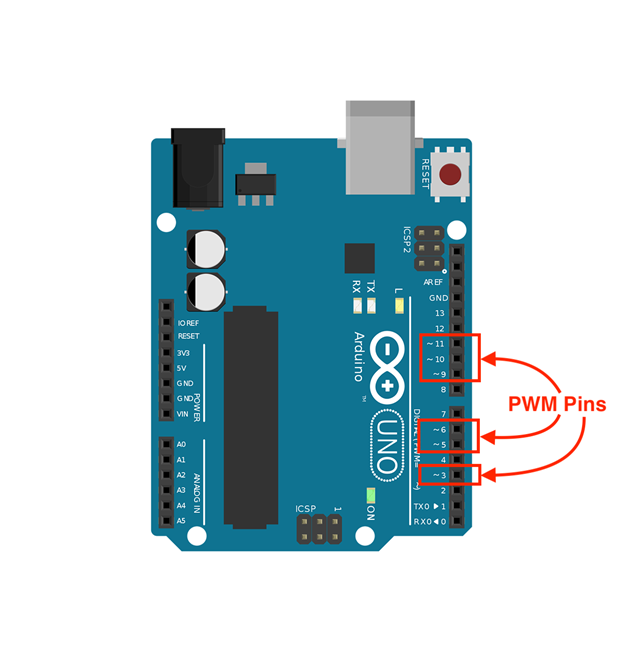
PWM Pins of Arduino Uno
The pins that are used to get the output of the Arduino in the form of pulses are called the PWM pins and its duty cycle varies from 0 to 255. The pins dedicated for PWM in Arduino Uno are 3, 5, 6, 9, 10, and 11. Below the image shows the PWM pins of Arduino Uno highlighted in red.
Conclusion
Arduino Uno which is the most popular Arduino board among the students as it can be used in a variety of embedded system projects and is easy to work with. However, to use this board, one must be aware of the board specifications and the pinout of the respective boards so that the board can be used effectively. For ease of the students and learners, we have described the purpose of each pin of the Arduino Uno in a very comprehensive way.
Source: linuxhint.com