Arduino Communication Protocol
Arduino Communication Protocols
By using Communication protocols, we can send and receive any sensor’s data in Arduino.
Some simple sensors like Infrared (IR) can directly communicate with Arduino but some of the complex sensors like Wi-Fi module, SD card module and Gyroscope cannot communicate directly with Arduino without any communication protocols. So, that is why these protocols are an integral part of Arduino communication.
Arduino have multiple peripherals attached to it; among them there are three communication peripherals used in Arduino boards.
Arduino Communication Protocols
Communication among different electronic devices like Arduino is standardized among these three protocols; it enables designers to communicate between different devices easily without any compatibility issues. Working of these three protocols are the same as they serve the same purpose of communication, but they differ in implementation inside a circuit. Further description of these protocols are discussed below.
UART
UART is known as the Universal Asynchronous Receiver Transmitter. UART is a serial communication protocol which means data bits are transferred in sequential form one after the other. For setting up UART communication we need two lines. One is the Tx (D1) pin of the Arduino board and the second one is the Rx(D0) pin of the Arduino board. Tx pin is for transmitting data to devices and Rx pin is used for receiving data. Different Arduino boards have multiple UART pins.
| Arduino Digital Pin | UART Pin |
| D1 | Tx |
| D0 | Rx |
To establish Serial communication using UART port we need to connect two devices in below shown configuration:
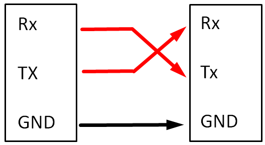
On Arduino Uno, one serial port is dedicated for communication which is commonly referred to as USB port. As the name suggests Universal Serial Bus, so it is a serial port. Using the USB port Arduino can establish communication with computers. The USB port is connected to onboard pins Tx and Rx of Arduino. Using these pins, we can connect any external hardware other than Computer through USB. Arduino IDE provides SoftwareSerial library (SoftwareSerial.h) which allows users to use GPIO pins as Serial Tx and Rx pins.
- UART is simple to operate with Arduino
- UART doesn’t need any clock signal
- Baud rate must be set within 10% limit of communicating devices to prevent data loss
- Multiple devices with Arduino in Master Slave configuration are not possible with UART
- UART is half duplex, which means devices cannot transmit and receive data at the same time
- Only two devices at a time can communicate with UART protocol
Serial Peripheral Interface (SPI)
SPI is an acronym of serial peripheral interface that is specially designed for microcontrollers to communicate with them. SPI operates on full-duplex mode which means SPI can send and receive data simultaneously. When compared with UART and I2C it is the fastest communication peripheral in Arduino boards. It is commonly used where high data rate is required like in LCD display and Micro SD card applications.
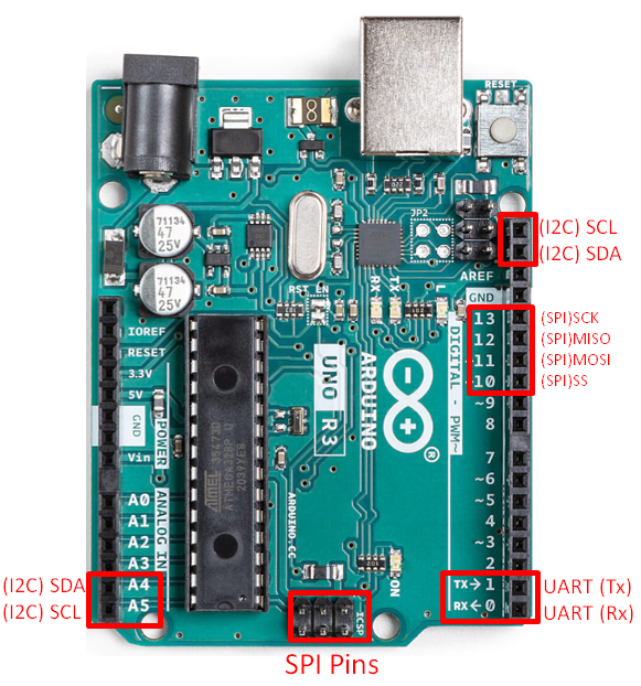
SPI digital pins on Arduino are predefined. For Arduino Uno SPI pin configuration is as follows:
| SPI Line | GPIO | ICSP Header Pin |
| SCK | 13 | 3 |
| MISO | 12 | 1 |
| MOSI | 11 | 4 |
| SS | 10 | – |
- MOSI stands for Master Out Slave In, MOSI is Data transmission line for Master to Slave.
- SCK is a Clock line which defines transmission speed and start end characteristics.
- SS stands for Slave Select; SS line allow Master to select a particular Slave device when operating in multiple Slave configuration.
- MISO stands for Master in Slave Out; MISO is Slave to Master transmission line for Data.
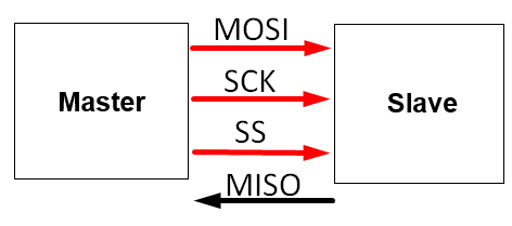
One of the main highlights of SPI protocol is Master-Slave configuration. Using SPI one device can be defined as Master to control several Slave devices. Master is in full control of Slave devices through SPI protocol.
SPI is synchronous protocol, which means communication is linked with common clock signal between Master and Slave. SPI can control multiple devices as Slave over a single transmit and receive line. All the Slaves are connected to Master using common MISO receive line along with MOSI one common transmit line. SCK is also the common clock line among Master and Slave devices. Only difference in Slave devices is each slave device is controlled through separate SS select line. This means that each Slave need an extra GPIO pin from Arduino board which will act as select line for that particular Slave device.
Some of the main highlights of SPI protocol is listed below:
- SPI is fastest protocol than I2C and UART
- No start and stop bits required like in UART which means continuous data transmission is possible
- Slave can be easily addressed due to simple Master Slave configuration
- For each Slave an extra pin is occupied on Arduino board. Practically 1 Master can control 4 Slave devices
- Data acknowledgment is missing like used in UART
- Multiple Master configuration is not possible
I2C Communication Protocol
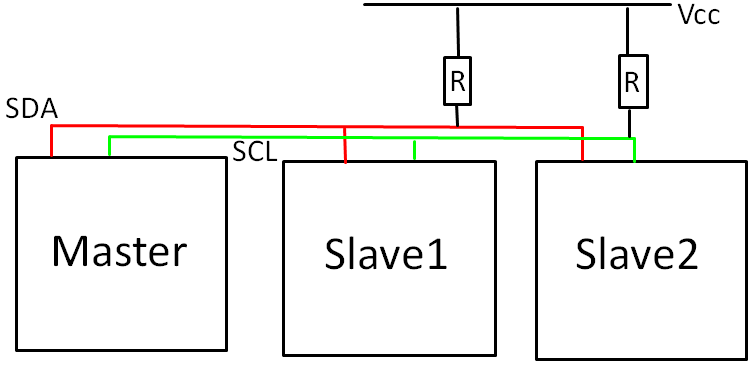
Inter Integrated Circuit (I2C) is another communication protocol used by Arduino boards. I2C is the most difficult and complicated protocol to implement with Arduino and other devices. Despite of its complication it’s offer multiple features that are missing in other protocols like multiple Master and multiple Slaves configurations. I2C allows connecting up to 128 devices to the main Arduino board. This is only possible because I2C share single wire among all the Slave devices. I2C in Arduino uses an address system, meaning before sending data to Slave device Arduino must first select Slave device by sending unique address. I2C uses only two wires reducing overall Arduino pin count, but the bad side to it is I2C is slower than SPI protocol.
| Arduino Analog Pin | I2C Pin |
| A4 | SDA |
| A5 | SCL |
At hardware level I2C is limited to only two wires, one for a data line known as SDA (Serial Data) and second one for Clock line SCL (Serial Clock). At idle state both SDA and SCL are pulled high. When data needs to be transmitted these lines are pulled low using MOSFET circuitry. Using I2C in projects it is mandatory to use pull up resistors normally a value of 4.7Kohm. These pull up resistors ensure that both SDA and SCL lines remain high in their idle start.
Some of the main highlights of I2C protocols are:
- Number of pins required are very low
- Multiple Master Slaves devices can be connected
- Only uses 2 wires
- Speed is slower as compared to SPI due to pull up resistors
- Resistors need more space in circuit
- Complexity of project increase with increase in number of devices
Comparison between UART vs I2C vs SPI
| Protocol | UART | SPI | I2C |
| Speed | Slowest | Fastest | Faster than UART |
| Number of devices | Up to 2 | 4 devices | Up to 128 devices |
| Wires required | 2(Tx,Rx) | 4(SCK,MOSI,MISO,SS) | 2(SDA,SCL) |
| Duplex Mode | Full Duplex Mode | Full Duplex Mode | Half Duplex |
| Number of Master-Slaves possible | Single Master-Single Slave | Single Master-Multiple Slaves | Multiple Masters-Multiple Slaves |
| Complexity | Simple | Can easily control multiple devices | Complex with increase in devices |
| Acknowledgment bit | No | No | Yes |
Conclusion
In this article, we have covered a comprehensive comparison of all the three protocols UART, SPI and I2C used in Arduino. Knowing all the protocols is important as it gives endless opportunities to integrate multiple devices. Understanding all the communication peripherals will save time and help to optimize projects according to the correct protocol.
Source: linuxhint.com